

Quad copter is a type of unmanned aerial vehicles (UAV) or drone being used on large scale. These are used for rescue operation, delivery, surveillance, defense, medical and agricultural purposes, etc. The main advantages of drones are compact size and easy controlling. In this article, we will learn how to design the quad copter (drone) using KK2.1.5 flight controller with the help of motors, flight controller, and chassis.
What is Quadcopter?
A quad copter is a multi rotor drone with 4 motors attached. Quadcopter stabilize its flight using electronic sensor and control system. There are two types of quad copters viz. 1- Plus configuration quad copter and 2- Cross configuration quad copter. In this tutorial, we will design a quad copter of X-shape. Both the shapes are stable but in forward flight, quad copter requires a yaw control input in forward flight. Yaw control authority is identical for both configurations but the pitch and roll control authority is up to about 30% greater in case of cross configuration. Quad copter depends on electronic sensors like accelerometer and gyroscope and control system to stabilize flight.
Components Required for Building Quadcopter
Frame:
Frame is the basic structure of the drone on which all the component are mounted together. The frames should be rigid so that it minimizes the vibrations from the motor. It consists of a center plate to which the electronic components and the four arms are attached to the center plate. In the image given below, we can see frame of quad copter.
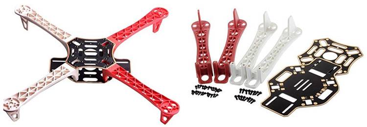
We are going to use f450 with the width of 450mm. It is made of glass fiber and durable nylon. It has two plates, one plate with the integrated PCB, so we can directly solder the ESCs. F450 arms are reinforced to prevent any damage; we can easily place the motor at the edge of the arms. We are using screws of type m2.5 size, which are socket head screws or allen screws.
Motors:
We have used brushless DC motor (BLDC) here. DC motor consists of coils and magnets which are used to drive the shaft and there is a brush over the shaft which takes care of switching the power direction in the coils. Brushless motors don’t have these brushes. They have coils at the center of the motor, which is fixed to the mounting. They contain a number of magnets mounted to a cylinder on outer side, which is attached to the rotating shaft. So, the coils are fixed. It means, the wires can go directly to them and therefore there is no need for a brush. Brushless DC motor spins at a much higher speed and uses less power than DC motor (at same speed). Also, there is no power loss due to brush transition. In the image given below. we can see 1000KV BLDC motor which has three input wire. We will connect these three wires with electronic speed controller (ESC).
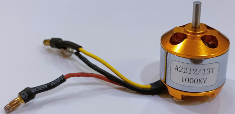
Brushless motor comes with Kv-rating. It means motor will spin at given RPM (revolutions per minute) if we give V voltage to motor without any load.
RPM = Kv * V
Here, we are using four brushless motor, which have 1000 Kv rating.
Propellers:
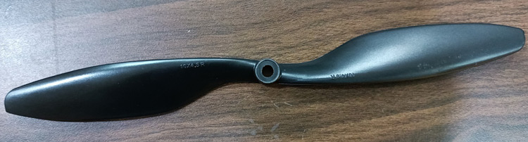
A Propeller is mounted on top of each brushless motor. Propellers come in many sizes and shapes. We are using (10*4.5) dimension propellers which mean its diameter is 10 and pitch is 4.5 inches. Diameter gives area but pitch gives an effective area. If we use a higher pitch propeller for the same diameter, the propeller will generate more thrust and lift more weight but it will also require more power. A high RPM provides more speed and maneuverability but lifts less amount of weight.
If we want to fly the drone stably with heavy object then we should use that motor which manages less revolution but provides more torque for which high pitch propeller should be used. To fly quad copter, we need 1:2 ratio for weight and thrust.
Power (watts) = Kp * D4 * P * RPM3
Where,
Kp = for midsized propellers Kp value is 1.2
D = Diameter of propellers
P = Pitch
Propeller’s position plays important role in flight of drone. We need to be aware about shape of propeller because propellers may look the same but they are not actually same, they may be mirror images of each other like our hands are mirror images of each other but they are not same.
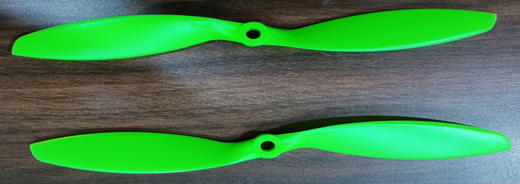
In above figure, propellers are looking same but both are different, both are mirror images of each other. Propeller should spin like this that they should scoop air downwards, because that will cause the drone to fly up. If propellers are pushing air upward then drone is going to be pushed to the ground. We should place our propellers such that they are scooping air downwards. Flat surface of propeller should be in the direction of motor rotation. If motor is rotating in clock wise direction then flat surface should be in front.
ESC (Electronic Speed Controller)
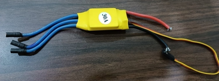
Brushless motor is 3 phase motor so it cannot be operated with DC power. ESC generates three frequency signals, with different but controllable phases continuously to keep the motor turning. It has a battery input and three phase output for the motor. We are using 30Amp ECSs here. In the image below, we can see how the ESC looks like. We are going to use four ESCs for four different motors.
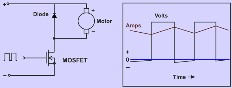
The controllers switching connection to the motor connected and disconnected around 2000 times per second by Pulse Width Modulation (PWM).MOSFET transistor is used as a switch instead of a mechanical switch. The speed of switching is fast and motors cannot detect it. If there is 24V battery connected, only half of the time, the motor sees the battery like 12 V and goes at half speed. The speed of switching also affects the motor inductance, which keeps the motor current flowing constantly. However, that current is only flowing half the time from the battery, so the battery current will be half the motor current. In below image, we can see the internal circuit diagram of ESC and its current(Amps) response with time.
Battery
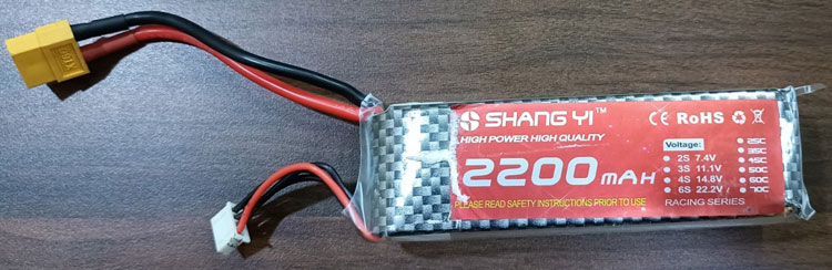
Lithium Polymer (LiPo) battery is commonly used for quad copters because of its light weight and high current rating. Here, we used 3 Cell LiPo batteries. Single Cell of LiPo battery can provide up to 3.6 V.
LiPo battery has 2200mAh capacity, 11.V (3 cells) voltage and 30C discharge rate. In the image given below, we can see 2200mAH LiPo battery. This is the image of 2200mAH LiPo battery.
LiPo battery has two characteristics parameter:
1- Capacity - It tells how much energy is stored in a battery.
2- Discharge Rate – It is also called C-rate and expressed in C-unit. It represents the rate at which the battery can discharge. The maximum current (Imax) that can draw from a battery is product of discharge rate and capacity.
Imax = Battery Capacity * Discharge Rate
We are using a battery which has discharge rate of 30C.
So, Imax = 2200mAh * 30C = 66 Amps
It means A 2200mAh 30C 3S LiPo can give up to 66 Amps of maximum current.
Transmitter and Receiver:
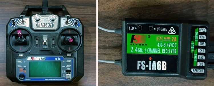
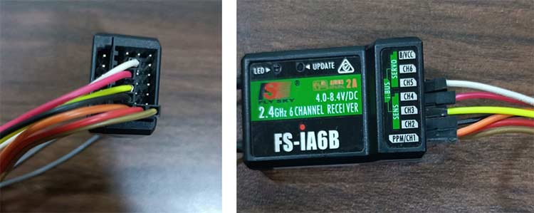
Transmitter works as a controller for a user. User can operate quad copter using this transmitter only. It is based on radio communication. The receiver is attached on the drone, receiver has antenna and with the help of antenna, it communicates with the transmitter. This is a completely wireless communication. The transmitter transmits a signal to the receiver and the receiver sends that signal to the flight controller. We are using FLYSKY transmitter and receiver here. This transmitter has range of 1500 meter but if we are using this transmitter at a place where magnetic interference is high, then range of transmitter will be decrease. You can see Everything you need to know about the FLYSKY FS-i6 Transmitter and Receiver for Effortless Drone Control article to know about all the functions of this transmitter and receiver.
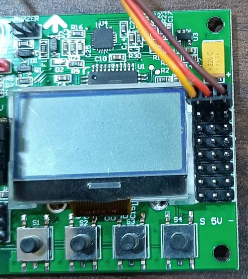
KK2.1.5 Flight Controller
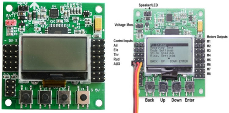
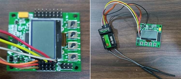
KK2.1.5 is a flight controller; the flight controller is also called the brain of the drone because with this all the operation of the drone is controlled. KK2.1.5 has ATMEL mega 664PA IC inbuilt inside it. It is 8-bit AVR RISC based microcontroller with 64k of memory. It has inbuilt accelerometer and gyroscope, 6050 MPU and auto level function. It has eight motor output at right side of board, we connect ESC here. It has 5 control inputs; these inputs are connected through receiver. It also has one LCD display in the middle, it will work as user interface for the drone. Its operating voltage is 1.8V to 5.5V and its input voltage is 4.8-6.0 V.
Kk2.1.5 is used to stabilize the quad copter during flight and to do this, it receives the signal from gyroscope (roll, pitch and yaw) and send these signals to processor (ATMEL mega 664PA) and then it passes control signal to ESCs and the combination of these signals instructs the ESCs to make fine adjustments to the motors rotational speeds which in-turn stabilizes the craft. Kk2.1.5 also uses signal from receiver and passes these all signals together to the processor (ATMELmega664PA) via the aileron, elevator, throttle and rudder user demand inputs. Once processed, this information is sent to the ESCs which in turn adjust the rotational speed of each motor to control flight orientation (yaw, right, left, up, down, backward, forward). In the video below, we have explained all the above mentioned components one by one.
Flight Control Mechanics for Quad Copter
The movement of the quad copter is controlled by varying the relative thrust of each of the 4 motor. Here, we are using quad copter of X shape. In this quad copter, the motor located on the same diagonal moves in the same direction either clock wise direction (CW) or counter clock wise direction (CCW). If we are going in a car then we can go front, back, left or right but when we are talking about flying system then we would not say the same. Flying system has different terminology viz. yaw, roll and pitch.
Before knowing the flying dynamics of a quad copter, we need to understand three main parameters of angular motion of quad copter, which are yaw, roll and pitch.
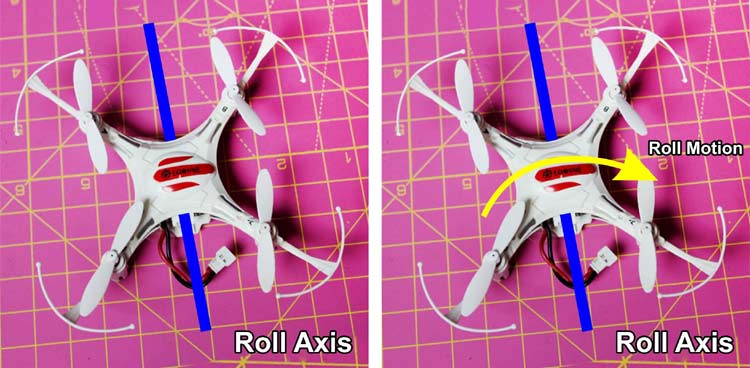
Roll:
The axis which runs back of the drone to the front of the drone is called a role axis and rotation about this axis is called role motion. This motion is also known as aileron. In the image given below, we can see roll motion.
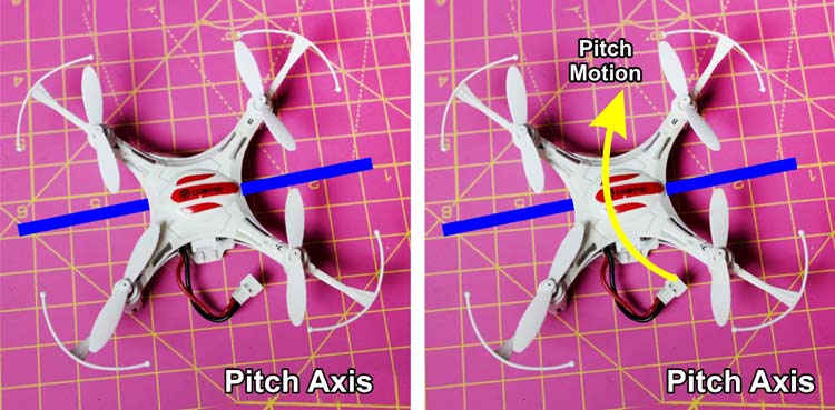
Pitch:
The axis which runs from left of the drone to the right of the drone is called pitch axis. The rotation about this axis is called pitch motion. It is also known as elevator motion. In image given below, we can see pitch motion.
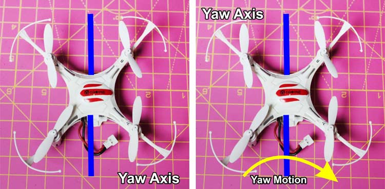
Yaw:
The axis which runs from top of the drone towards bottom of the drone is called yaw axis. The rotation about this axis is called yaw motion. It is also known as rudder. In image given below, we can see yaw motion.
With the help of image given below, we can understand all the three motions together.
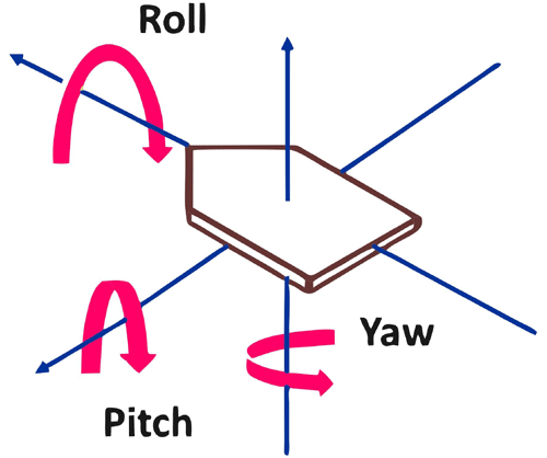
These are not lateral movement themselves but rotation along the three different axes. Even lateral movement is a result of rotation along these axes. To understand control of the drone, we first need to understand different forces acting on the drone. If thrust = weight (mg), then quad copter will remain in equilibrium. If thrust > weight (mg) then drone will go upward and if thrust < weight (mg) then drone will go downward.
While going upwards, the direction of the thrust is the direction of the motion of the drone, so to change the direction of the drone’s motion we need to change the direction of the thrust and this is logic behind the drone motion.
Motion in Forward and Backward Direction:
If we want to move drone in the forward direction, we need to generate the component of thrust in forward direction. This is done by increasing the power of the rare motors and reducing the power of the front motors. If we want to move drone in backward direction, we reduce the power of the rare motors and increase the power in the front motors.
Motion in Left and Right Direction:
To move the drone to the left, we generate the component of thrust in the left direction. This is done by increasing the power of the right motors and reducing the power of the left motors. To move the drone to the right, we increase the power of the left motor and reduce the power of the right motor.
Yaw Motion of Quad Copter:
For yaw movement, things can get a bit tricky, when we want to yaw drone in CW direction, we will increase the power to the counter clock wise propellers the resulting reactive torque will yaw the drone in the clock wise direction. If we want to yaw drone in CCW direction, we will increase the power to the clock wise propellers and the resulting reactive torque will yaw the drone in the counter clock wise direction, so to control the motion of quad rotor, we control the power that we give to its motor.
In the video below, we have explained the quad copter’s flight control mechanics through a sample drone

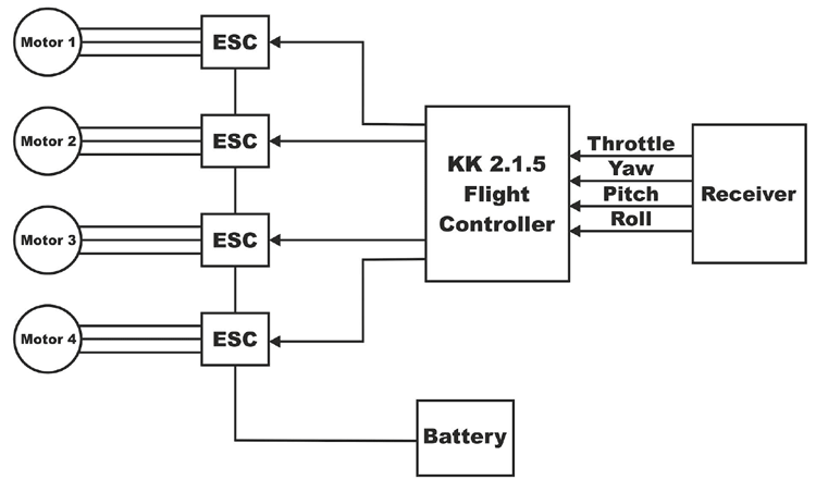
Block Diagram of Quadcopter
As we can see in below block diagram, all the motors are connected with KK2.1.5 through ESCs. Accelerometer and Gyroscopes are shown outside the KK2.1.5 board but it is built inside the board itself. A receiver is connected directly with KK2.1.5 board. In the image given below, we have shown the block diagram of quad copter.
Flight Dynamics of Quad Copter
To fly the drone, we have only 4 types of input. These four inputs are controlled by giving more or less power to the motor.
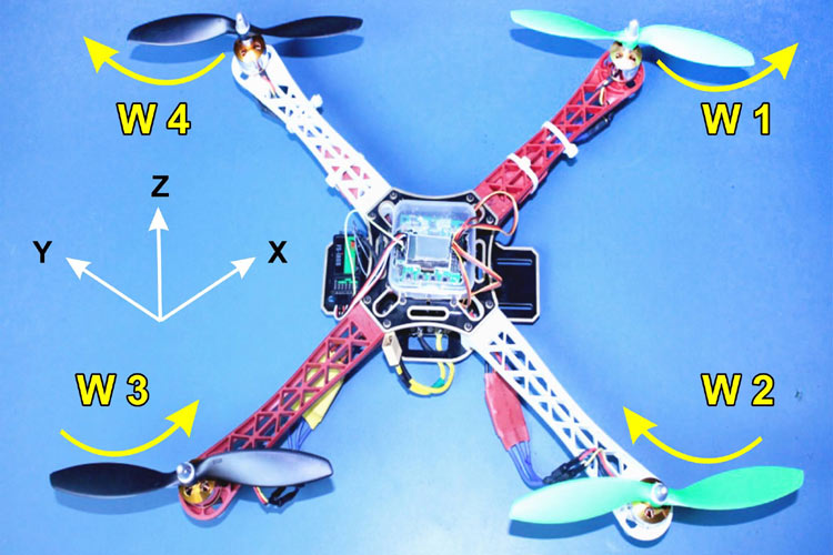
There are 4 motors here, motor 1 & 3 are rotating in CW direction and motor 2 & 4 are rotating in CCW direction. Ꞷ1, Ꞷ2, Ꞷ3, Ꞷ4 are the angular speed of motor 1 , motor 2, motor 3 & motor 4. l is the distance between diagonally opposite motors and Z axis is perpendicular to the surface.
Each motor provides an upward thrust in Z direction.
Thrust α Ꞷ2
Thrust = KꞶ2
Where K is lift constant.
Each motor provides an upward thrust in Z- direction.
Force in Z direction (upward direction):
Fz = K (Ꞷ12 + Ꞷ22 + Ꞷ32 + Ꞷ42)
Torque in X, Y and Z direction:
Tx  = K * l * (Ꞷ42 - Ꞷ22 )
Ty  = K * l * (Ꞷ32 - Ꞷ12 )
Tz = B * l * (Ꞷ12 - Ꞷ22 + Ꞷ32 - Ꞷ42)
where B is drag constant
What about Fx & Fy ?
In quad copter, we can perfectly induce rotation motion. We can induce torque in X, Y and Z direction but we can induce force in only Z direction. We cannot induce Fy and Fz directly. Motors cannot induce force in the X, Y direction.
If we want to move quad copter along the X & Y direction then we need to rotate the quad copter a little bit by an angle about X or Y axis, then A component of force is going to be act along X, Y and Z axis. We can indirectly induce motion in X, Y direction by rotating quad copter.
So, controlling the quad copter is bit complicated because we cannot directly get motion in X & Y direction, We need to first induce a rotation and then force will be act in X & Y direction.
We have for control variable or four inputs
Fz , Tx , Ty , Tz
But we have to control six parameters or Six outputs
X, Y, Z, θ (Roll), Փ (Pitch), ψ (Yaw)
On transformation using inverted Matrix Method we get,
Ꞷ12 =   (1 / 4k) *  Fz   –  (1 / 2kl) * Ty – (1 / 4b) * Tz
Ꞷ22 =   (1 / 4k) *  Fz   –  (1 / 2kl) * Tx + (1 / 4b) * Tz
Ꞷ32 =   (1 / 4k) *  Fz   +  (1 / 2kl) * Tx – (1 / 4b) * Tz
Ꞷ42 =   (1 / 4k) *  Fz   +  (1 / 2kl) * Tx + (1 / 4b) * Tz
In the video below, we have explained the flight dynamics of a quad copter through a sample drone.
Setup and Tuning of KK2.1.5 Flight Controller
Kk2.1.5 multi rotor LCD flight controller board is built on ATML644 PA. Right hand side of board has 8 outputs of which we will be using four only output to connect ESCs directly. We are going to use quad copter so we have used only four output pins.
ESC’s Connections:
Output pins have 3 pins in each row. Right most all pins are ground. All center pins are Vcc (5 volt). And all firsts’ pins are signals. Connect all the four ESCs wire to the first four output pins of KK2.1.5 board. Connection between ESCs and KK2.1.5 board should be like below table.
|
ESCs |
KK2.1.5 Board |
|
Ground (Brown wire) |
Ground (Right most pin |
|
Vcc (Red Wire) |
Vcc (Central Pin) |
|
Signal (Yellow Wire) |
Signal (Left pin) |
In figure below, we can see connection of ESCs with KK2.15. Here, we have connected only 1 ESCs, like this we will connect all four ECSs with KK2.1.5 board.
Receiver Connections:
Inputs pins are at left side of LCD display. There are 5 connection here, these pin will connect with Receiver. Receiver pins and KK2.1.5 input pins should be connect as follows:
|
Receiver Channel |
Connecting Wire Color |
KK2.1.5 (Input Pins) |
|
Aileron (CH1) |
Orange (Signal), Red (Vcc), Green (Ground) |
Aileron (1st Row) |
|
Elevator (CH2) |
Black |
Elevator (2nd Row) |
|
Throttle (CH3) |
Yellow |
Throttle (3rd Row) |
|
Rudder (CH4) |
Pink |
Rudder (4th Row) |
|
AUX1 (CH5) |
White |
AUX1 (5th Row) |
We will connect receiver’s first channel (CH1) with three connection wires and rest channel will be connected through single wire only because there is no need to connect Vcc and ground for other channels. According to the above table, receiver end connection should look like what you can see in the images below.
According to the above table, KK2.1.5 board end connection should look like what you can see in the images below.
In the video below, we have explained the connection of the ESCs and the receiver to the kk2.1.5 flight controller.
BLDC motor Setting:
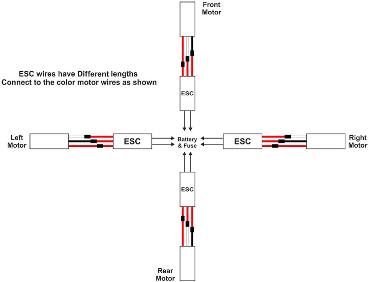
Motor one and three should rotate anti clock wise direction and motor two and three should rotate in anti clock wise directions. We are going to set direction of all motor using fly sky transmitters. First connect battery to the power dean connector. We will connect first motor ESC to channel 3 of Receiver, channel 3 is always throttled. Now, switch on the transmitter and move slightly the throttle then motor will rotate. Now, observe the direction of motor. If we see that the direction is opposite, we will reverse the end wires of motor and ESC connection. Now, move the throttle again and we can see that motor is rotating in the desired direction. Now, repeat the same procedure for each motor. Motor and ESCs both have 3 wires, we are going to connect motor and ESC like below image.
In the video below, we have explained the connection of ESCs and BLDC motor.
KK2.1.5 Setup
For setting up KK2.1.5 board, first keep the transmitter on and ensure that the receiver is bound to transmitter. There are four buttons at the bottom of the KK2.1.5 board S1, S2, S3 and S4. Using these buttons, we will interact with LCD display.
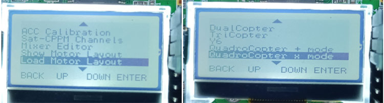
Step-1 First go to menu by pressing S4 then go to load motor layout then select quad copter X mode and setup quad Copter at X – mode. Check all the motor directions here.
Step-2 Next is ACC calibration, for which we have to place quad copter on the plane level surface and select the Acc Calibration that is to calibrate accelerometer. Click on S4, this is auto calibration.
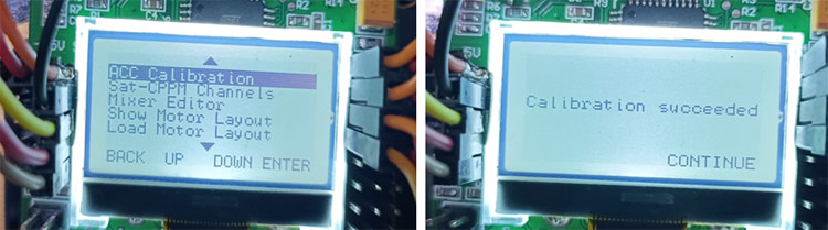
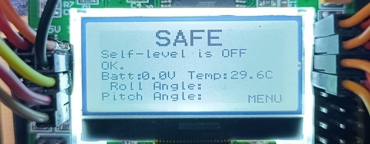
As soon as Acc calibration over, we can pull out the power and provide the power again. It will be showing safe on LCD display which means, it has changed from error to safe.
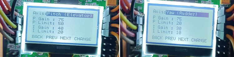
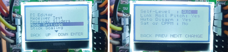
Step-3 Now, go to the PI editor. Here, we have to set P (gain / limit) and I (gain / limit) of aileron (Roll), elevator (Pitch) and rudder (Yaw). P gain is proportionality gain that represents sensitivity and responsibility. Higher P means sharper control and lower P means softer one.
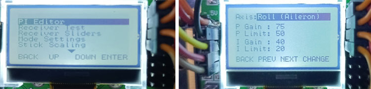
I is integral gain that represents how well it holds the altitude. Once PI setting has been done go to the mode setting.
Step-4 In the mode setting, set the self level to AUX.
Step-5 Now go to miscellaneous settings, here we will set Alarm 1/10 volts.
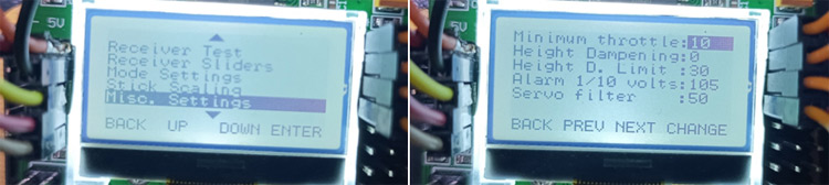
To set alarm 1/10 volts, we need to do following calculations.
3-Cell LiPo battery of 11.1 volts use a value 3.60 volt per cell to denote an empty batter then set the value (in 1/10’s) to (3.6 * 3 * 10 = 108) and when the supply voltage drops to 10.8 volts the alarm will sound.
Step-6 Now, we fo the calibration of ESCs. First turn the transmitter with throttle to minimum then move throttle to maximum and keep pressing S1 and S4 switches and then connect the battery to the quad copter, now we will get two beep sound and we will put the throttle down which leads to single beep sound. With this, the calibration process gets over .
Step-7 To arm the quad copters, keep the throttle at left hand side, once the quad copter is armed, we can fly quad copter.
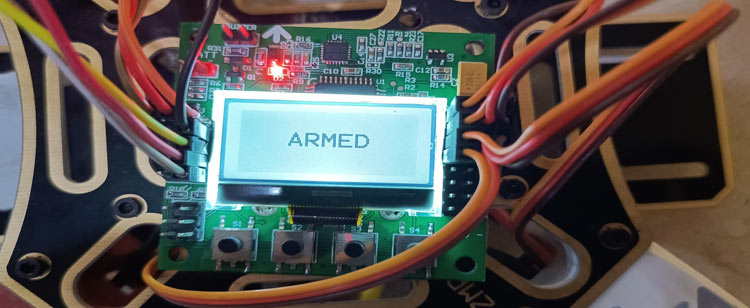
Now quad copter is ready to fly. Keep the throttle at right side.
In the video below, we have explained the setup of the KK2.1.5 flight controller setup step by step.
PI Tuning in Quad Copter
Very low P Gain:
It is very hard to control the quad copter and quad copter lacks overall stability. Control inputs feel imprecise and slow when the craft responds. When quad copter will fly, it will be easy to over correct a command and craft will be jittery.
Very High P & I Gain:
Quad copter will suffer from side to side oscillation. Quad copter will easily gain or loose height but it will be hard to maintain the given height. Quad copter will shake and oscillate with low frequency.
Correct P Gain:
We can simply operate the quad copter, and it will fly in a stable manner. It can take off quickly and gracefully, hovering in a place. If we want to fly a quad copter acrobatically, we should increase the P setting slightly from its stable flight value and decrease the I setting slightly from its stable flight value; if we want gentle smooth flight, we should decrease the P setting slightly from its stable flight value and increase the I setting slightly from its stable flight value.
Proportional Gain coefficient (Kp):
Kp plays important role for relatively stable flight. Kp determines mix between on-board control from the gyros and user stick inputs. On increasing the Kp value quad copter will become more sensitive, reactive to angular changes and may oscillates with a high frequency. On decreasing the Kp value, quad copter will be sluggish and difficult to keep steady.
Integral Gain Coefficient (Kc)
Kc increases the precision of an angular position. For example, when the craft is disturbed by wind and its angular position changes by say 10 degrees, it in theory remembers how much the angle changed and will attempt to return by 10 degrees. It is useful with irregular wind and turbulence from motor. When the Kc value will be high then quad copter will begin to have slow reactions and it will decrease the effect of the Kp but quad copter starts oscillate at lower frequency when Kp value set to be high.
In this tutorial, we have designed a quadcopter with the help of KK2.1.5 flight controller. Here, we have explained from setting up the controller to tuning the controller. In next part, we will address some of the problems to make a quad copter fly smoothly.

very useful