
The biggest crisis we are heading into is the climate change due to excessive use of fossil fuels and to overcome these issues, we have only one solution that is utilizing Renewable Energy. Renewable energy is a type of energy that is harnessed from the nature without causing ill effects to the environment. One of the most prominent kind of renewable energy is solar energy. Solar radiation from the sun is collected by the solar panels and converted into electrical energy. The output electrical energy depends on the amount of sunlight falling on the solar panel.
If you have just started to work with Arduino do check out our Arduino Projects and Tutorials. We have a collection of almost 500+ Arduino projects with Code, Circuit Diagram, and detailed explanations completely free for everyone to build and learn on their own.
Traditionally, solar panels are fixed and the movement of sun over the horizon means that the solar panel does not harness maximum energy most of the time. In order to maximize the power from the solar panel, the panel should face the sun all time. In this project, we will make a sun tracking system which will help the solar panels to generate maximum power. In some of our previous articles, we have built simple system to track power generated from solar panel and other solar energy related projects. You can check those out if you are looking for more projects on solar power.
How does a Solar Tracker Works?
You must be wondering how does it work? As discussed earlier, the solar panel should face the sun to harness maximum power. So, our system has two steps, first is to detect the position of sun and second is to move along with it.
Detecting the position of the Sun:
We measure the intensity of light with LDRs using Arduino and compare the intensity of light falling on both LDRs. The LDRs are placed on the edges of the solar panel as shown in the figure below.
Based on the intensity of light on the LDR, we give the signal to the servo motor to cause the movement. When the intensity of the light falling on the right LDR is more, the panel turns towards the right and if the intensity is higher on the left then the panel slowly turns towards the left side.
![]()
Consider a scenario of a beautiful winter morning, the sun rises from east side and therefore it has more light intensity than the west side, so the panel moves towards to east side. Throughout the day it will track the sun and by the evening, sun has moved towards the west, hence it will have more intensity than the east direction so the panel will face the west direction.
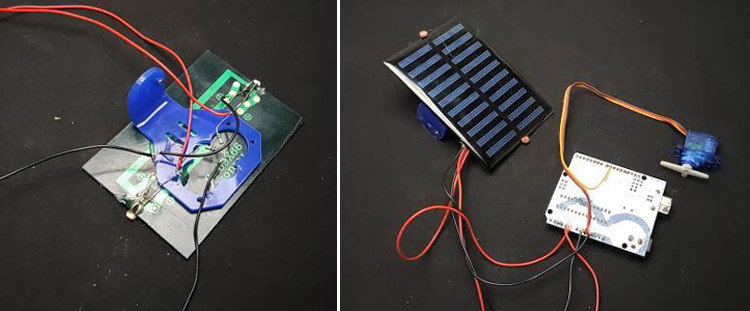
Components Required for Making the Solar Tracker
![]()
- 1 x Arduino Uno
- 1 x Servo motor
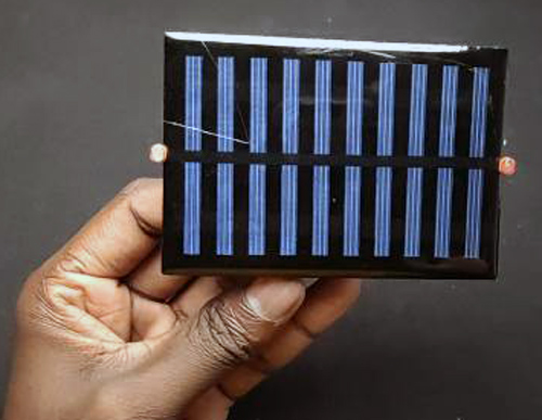
- 1 x Solar panel
- 2 x LDR
- 2 x 10k Resistor
- Jumper wires
- 1 x MDF board
Servo Motor:
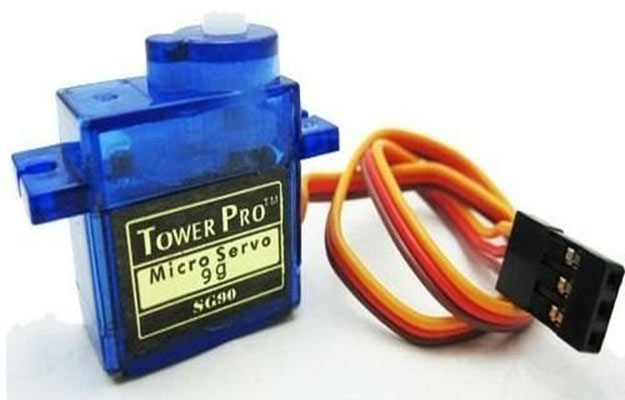
Servo motor is used to rotate the solar panel. We are using servo motor because we can control the position of our solar panels precisely and it can cover the whole path of sun. We are using a servo motor that can be operated with 5volt.
Light Dependent Resistor (LDR):
A light-dependent resistor is made from semiconductor material having light-sensitive properties and hence are very sensitive to light. The resistance of LDR changes according to the light that falls on it and it is inversely proportional to the intensity of light. That is resistance of the LDR will increase at high-intensity light and vice versa.
Schematics and Connection of the Solar Tracker
The connection of the circuit is very straightforward. Here, I used an Arduino Uno as controller and connected the 2 LDRs to analogue pin A0 and A1 respectively. Pin 9 of Arduino is connected to the servo motor. Since, we have used a 5V servomotor, we don’t require any external power supply because all the components can easily be powered the Arduino itself. All the connections are shown in the figure below.
![]()
Assembling the Solar Tracker
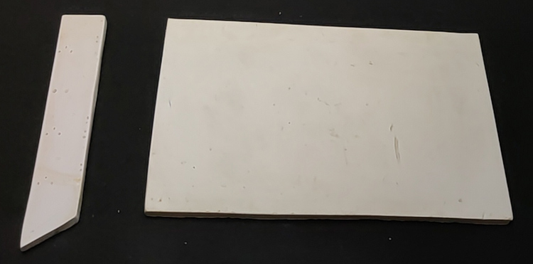
The first step before assembling our solar tracker is to construct the base. For building the base, I am going to use a MDF board. First step is to cut and make rectangular pieces of 12*8cm and 12*2cm from the MDF board as shown in the figure.
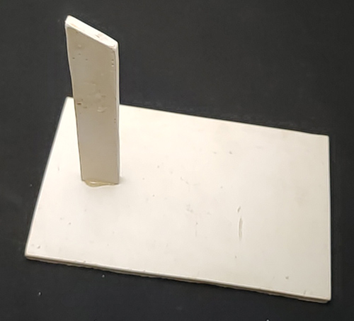
Then stick 12*2cm piece vertically to the 12*8cm piece as shown in the image.
Next step is to attach the solar panel with the servo motor, for that we require the L-shaped contraption. For this, I am using a plastic piece, you can also make this by bending a plastic sheet or aluminum sheet and finally glue the solar panel to your contraption.
Note: If you are going to make a tracker for a large solar panel then you should use different materials for bases such as aluminium or wood.
Now, we need to affix the LDRs on opposite sides of the solar panel and to do that, I glued the LDRs to the panel. Then, I connected the 10k resistors to one any leads of both LDRs and the other side of resistor should be connected to the ground. These are acting as pull-down resistor. Second terminal of the LDRs are directly connected to the 5v output. The output of each LDR, I connected it to A1 and A2 pins of Arduino.
Next step is to connect the servo motor, a servo motor has three wires, i.e. ground, V_in and a signal wire. I connected the V_in pin to the 5volt of Arduino, ground to the common ground and the signal wire to pin-9 of Arduino. That's all about the circuit.
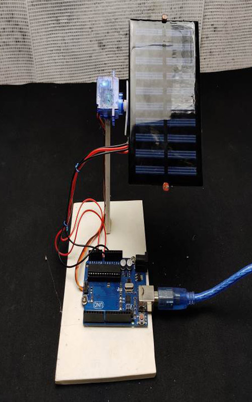
Now, all we have to do is assemble everything. First, I glued the Arduino on the base sheet. Then I attached the servo motor to the vertical section using glue gun. Finally, I fixed the solar panel with the servo motor’s hand and secured it with a screw.
![]()
Let’s see how does the code works?
The complete code for this project can be found at the bottom of this page. First step before writing the code is to download the Servo Library. We need a servo library to control the motion of the servo. The step-by-step explanation of the program is given below.
#include <Servo.h>
Servo servo ;
First, I included the servo library and created a servo object and named it as ‘servo’.
int eastLDR = 0;
int westLDR = 1;
int east = 0;
int west = 0;
int error = 0;
Here, I have assigned the analogue pins A0 and A1pins for LDR and declared the variables for sensor values.
int calibration = 0;
This variable is for calibrating the system, if you are using exactly same LDRs on both sides then you can leave it as zero. But if you are using different LDRs then you should use this to calibrate. To calibrate, follow the instruction in next paragraph.
Serial print the sensor values and check the reading of each sensor in the noon or place a light source just above the solar panel. If the reading shows the same values, then you can leave this as it is and if it shows any difference, then you have to copy those values here.
int servoposition = 90;
This variable is to store the servo position.
void setup()
{
  servo.attach(9);
 }
In the section, I have defined the servo pin as pin 9
east = calibration + analogRead(eastLDR);
west = analogRead(westLDR);
In the loop section, first step is to read the LDR values using the analogue read function of Arduino and store it in east and west variables.
if(east<350 && west<350)
  {
 while(servoposition<=150)
  {
servoposition++;
servo.write(servoposition);
delay(100);
    }
This if condition is for turning the solar panel back to the east side, i.e. if both the LDRs read low value then the panel moves towards the east side.
error = east - west;
Here, we calculate the difference between east and west readings. If the error value is positive that means east has more intensity and if the error is negative then west has higher intensity of light. So, according to this error value, we can rotate the servo to the low-intensity side.
if(error>30)
  {
 if(servoposition<=150)
{
servoposition++;
 servo.write(servoposition);
}
  }
If the error is positive and greater than 30, it means that the east side has more intensity. So, initially the system will check the starting position of servo and if it is less than 150 degrees then it rotates to the east direction. You can adjust these angles according to your system.
 else if(error<-30)
  {
 if(servoposition>20)
{
 servoposition--;
 servo.write(servoposition);
  }
If the error is negative and less than -30 that means the west side is more intense, hence servo rotates to the west side.
So, that's all about coding. Now you can open this code on your Arduino IDE and upload the sketch to your Arduino.
![]()
I hope that you enjoyed this project. It has a lot of application in real life and it is implemented in a lot of solar farms and individual solar harnessing setups. You can enhance the scope of this project by replacing the 5V servo motor with a high torque servo motor and connect it using a relay and power the servo from an external source. As mentioned above, if you are having bigger solar panels, then you will have to use stronger material such as aluminum for base.
Complete Project Code
#include <Servo.h>

Servo servo ;

int eastLDR = 0;

int westLDR = 1;

int east = 0;

int west = 0;

int error = 0;

int calibration = 600;

int servoposition = 90;

void setup()

{

  servo.attach(9);

}

void loop()

{

  east = calibration + analogRead(eastLDR);

  west = analogRead(westLDR);

  if (east < 350 && west < 350)

  {

    while (servoposition <= 150)

    {

      servoposition++;

      servo.write(servoposition);

      delay(100);

    }

  }

  error = east - west;

  if (error > 15)

  {

    if (servoposition <= 150)

    {

      servoposition++;

      servo.write(servoposition);

    }

  }

  else if (error < -15)

  {

    if (servoposition > 20)

    {

      servoposition--;

      servo.write(servoposition);

    }

  }

  delay(100);

}

Hi, nice project! I am having issues with the servo not tracking. It only rotates to one side and stays there. Can you point me towards the right direction for troubleshooting it? Thanks!