

We know that voltage, current, and power are measured in volts, amps and, watts and voltmeter, ammeter, and wattmeter are used to measure these parameters. Though these measuring instruments are manufactured with the care they may still give error readings at the customer end. So these instruments are calibrated to minimize the error. Here in this article, we will explain how to calibrate Voltmeter, Ammeter, and Wattmeter using a potentiometer.
Before going into detail, let us first discuss the important concept used in this article.
If we have two voltage sources of the same value connected in parallel as shown below, then there will be no current flow between them. This is because the potential values of both sources are the same and neither of the sources can push charge on to the other. So in the circuit, the galvanometer does not show any deflection.
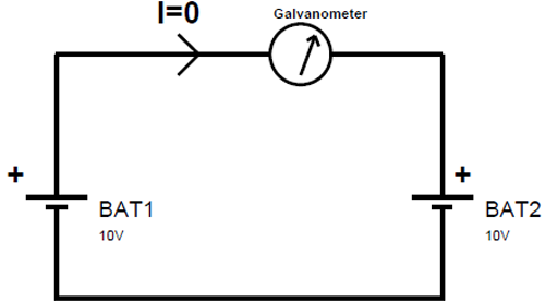
We will use the same phenomenon of balancing two voltage sources in the calibration process.
Calibration of Potentiometer
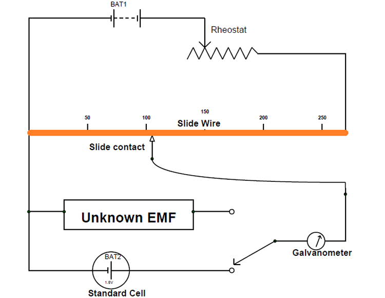
The above figure shows the circuit diagram for potentiometer calibration.
In the figure, a standard cell with voltage 1.50V is used which doesn’t produce voltage fluctuations even in millivolts upon loading. This kind of stable source is necessary for calibrating potentiometer without any error.
The conductive scale is scaled accurately to avoid miss reading during measurements. The conductive scale also has a smooth surface with clean-cut dimensions for equal resistance distribution along all its length.
The rheostat is present for adjusting the flow of current in the circuit loop and thereby we can adjust the voltage drop per unit length along the conductive scale. A galvanometer is also connected here for visualizing the defection that happens in case of current flow between the standard cell loop and conductive scale loop. The unknown EMF here is connected to the galvanometer for measurement after the calibration of the potentiometer.
Working:
First, turn ON the power and adjust the rheostat to allow a current of a few hundred milliamperes to flow in the main circuit loop. Because the conductive scale is also in the main loop the same current flows through it producing a voltage drop. Although the voltage drop appears across the metal scale will be distributed all along its body evenly.
After the appearance of the voltage drop along the conductive scale, if we take the sliding contact and move along the metal scale from zero, then current flows from secondary circuit to primary circuit because of circuit imbalance. And as the sliding contact moves further away from zero, the magnitude of this current flow decreases. This is because, as the contact area increases, the voltage drop across the scaled area will get close to the voltage of the standard cell. So at a certain point, the voltage drop across the scaled area will be equal to the voltage of the standard cell and at that point, there will no current flow between two circuits.
Now that a galvanometer is connected in the secondary circuit, it will show a deviation on its display because of current flow and higher the current more will be the deviation. Based on this, the galvanometer will show no deviation only when both the circuits are balanced and this is the state we will be trying to achieve for calibrating the potentiometer.
For better understanding, let’s see the circuit shown below which shows the state of balance.
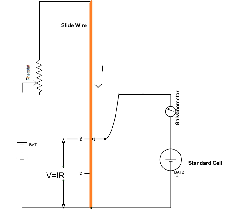
If we assume the resistance of metal contact from length 0 to 100 cm as ‘R’, then the voltage drop across the entire 100cm length metal contact is V=IR. Since we assumed a balanced circuit, this voltage drop ‘V’ must be equal to the voltage of the standard cell and there will be zero deviation in galvanometer reading.
Now by measuring this exact length at which galvanometer shows zero, we can calibrate the potentiometer scale based on the standard cell voltage value.
So 1cm length of scale holds = 1.5v/100cm = 0.005V = 5mV.
After knowing the voltage drop per centimeter in the potentiometer scale, connect the unknown voltage to the secondary circuit and slide the contact to measure the length at which we will have zero deviation. After knowing this length of scale at which balance takes place, we can measure the value of unknown EMF as,
V = (length of contact) x (5mV).
Applications of Potentiometers
In addition to the measurement of unknown voltage, the potentiometer can also be used to measure the current and power, it just needs a couple of extra components for measuring them.
Other than measuring voltage, current, and power, the potentiometers are mainly used for calibration of voltmeters, ammeters, and wattmeter. Also, since the potentiometer is a DC device, the instruments to be calibrated must be DC moving iron or electrodynamometer types.
Calibration of Voltmeter using Potentiometer

In the circuit, the most important component for the calibration process is a suitable stable DC voltage supply. This is because any fluctuations in supply voltage will cause an error in the voltmeter calibration thereby leading to an entire failure of the experiment. So standard voltage cell with stable terminal value is taken as a source and connected in parallel with voltmeter which needs to be calibrated. The two trim pots ‘RV1’ and ’RV2’are used for adjusting the voltage that is to appear across the voltmeter as shown in the figure.
A voltage ratio box is also connected in parallel with the voltmeter to divide the voltage across the voltmeter and get appropriate value suitable for connecting the potentiometer.
With the entire setup in place, we are ready for testing the accuracy of the voltmeter. So to start, just provide the power to the circuit to get a reading on the voltmeter and an unknown voltage at the voltage ratio box output. Now we will use a calibrated potentiometer to measure this unknown voltage.
After getting the potentiometer reading, check whether the potentiometer reading matches the voltmeter reading. Since potentiometer measures the true value of voltage, if the potentiometer reading does not match with the voltmeter reading, then a negative or positive error is indicated. And for correction, a calibration curve can be drawn with the help of the readings of voltmeter and potentiometer.
Also, for accuracy of measurements, it is necessary to measure voltages near the maximum range of the potentiometer as far as possible.
Calibration of Ammeter using Potentiometer

As mentioned above, we will use a suitable stable DC supply voltage to avoid the errors in calibration which do not produce voltage fluctuations during the entire experiment. A rheostat is used for adjusting the magnitude of the current flowing through the entire circuit. Also, a standard resistance ‘R’ of suitable value with sufficient current-carrying capacity is placed in series with the ammeter (which is under calibration) for getting a voltage parameter which relates to the current flowing in the circuit.
Now after the power is turned ON, a current ‘I’ flows through the entire circuit and with this current flow reading will be generated by the ammeter present in the loop. Also, a voltage drop will take place across the standard resistance ‘R’ because of this current flow.
Now we will use a potentiometer to measure the voltage across the standard resistor and then use ohms law to calculate the current through the standard resistance.
That is the current I=V/R
Where
V=voltage across the standard resistor measured by the potentiometer,
And R=resistance of a standard resistor.
Since we are using the standard resistor, the resistance will be accurately known and the voltage across the standard resistor is measured by the potentiometer. The calculated value will be the accurate value of the current flowing through the loop. Then compare this calculated value with ammeter reading to check the accuracy of the ammeter. If there are any errors, we can make necessary adjustments for the ammeter to rectify the errors.
Calibration of Wattmeter using Potentiometer

As mentioned above for an accurate calibration process, we will use two suitable stable DC voltage power supplies as sources. Usually, low voltage supply is connected in series with the current coil of a wattmeter and a moderate voltage supply is connected to the potential coil of the wattmeter. A rheostat in the top circuit is used for adjusting the magnitude of the current flowing through current coil and trim pot in the bottom circuit is used for adjusting the voltage across the potential coil.
Do remember that a trim pot is preferred for adjusting the voltage and rheostat is preferred for adjusting the current in a circuit.
Also, a standard resistance ‘R’ of suitable value and sufficient current-carrying capacity is placed in series with the current coil of the wattmeter. And this standard resistance will generate a voltage drop across it when current flows in the current coil circuit.
After the power is turned ON we will get two unknown voltage readings, one is at the voltage divider output and the other is across the standard resistance ‘R’. Now if a potentiometer is used to measure the voltage across the standard resistor then we can use ohms law to calculate the current through the standard resistance. Since the current coil is in series with the standard resistance the calculated value also represents the current going through the current coil. In a similar way, use the potentiometer second time to measure the voltage across the potential coil of the wattmeter.
Now that we have measured the current through current coil and voltage across the potential coil using a potentiometer, we can calculate the power as
Power P = Voltage reading x Current value.
After calculating we can compare this calculated value with wattmeter reading to check for errors. Once the errors are found, make necessary adjustments to the wattmeter to adjust the errors.
This is how a potentiometer can be used to calibrate Voltmeter, Ammeter, and wattmeter to get accurate readings.

It is is a very good effort for electronics lover and hobbiest