I have built up the following circuit to control volatge on a variable power supply. It will be used in conjunction with a similar current control circuit which is why it is set up to turn MOSFET off rather than on.
It works to control voltage up an down using 0.033 gain from a 5V control voltage, DAC eventually, but now just potentiometer for testing.
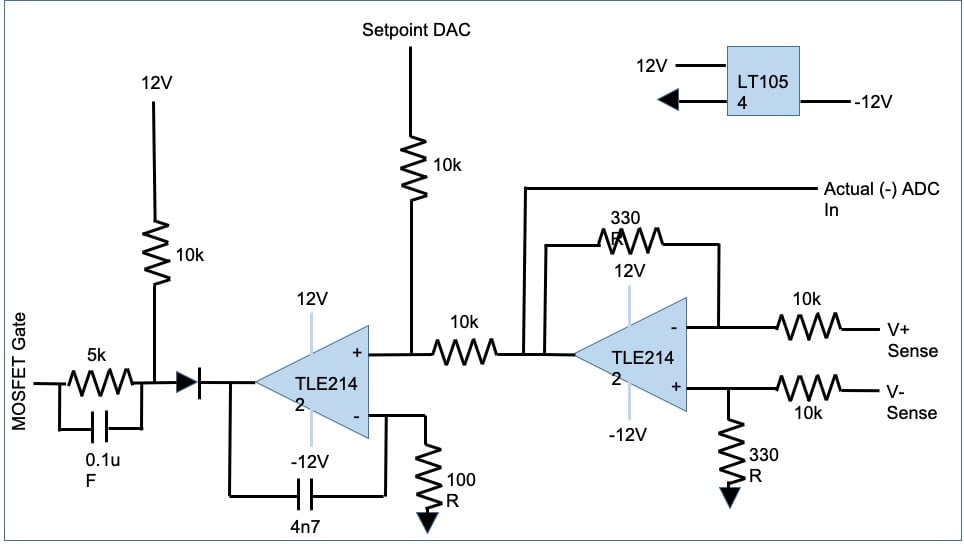
The issue is I can't get it to turn off. At 0V input on setpoint I get the following readings:
Input Sense (relative to each other) 200mV
Output of first Op Amp -6.6mV (relative to analog Gnd); which is spot on for 0.033 gain
But the input of the second Op Amp + is 0V (relative to analog Gnd)?
The second Op Amp - is also 0V and the output is 2.052V (relative to analog Gnd)
This means the MOSFET gate volatge is 2.565V. Having tested this seperately it requires below 1.907V to turn off.
How can I solve this?


ok. What you have provided on the setpoint of DAC?
Disconenct the diode and mosfet circuit, how much votlage are you getting across the opeamp output?

Sourav Gupta
Joined February 12, 2018 696Monday at 02:11 PM
What is the partnumber of the Mosfet?