

We can consider the Volume Meter as an Equalizer, which is present in the Music systems. In which we can see the dancing of lights (LEDs) according to the music, if the music is loud, equalizer reaches to its peak and in low music it remains Low. We have also built a Volume Meter or VU meter, with the help of MIC, OP-AMP and LM3914, which glows the LEDs as per strength of the sound, if sound is low, lesser LEDs will glow, and if sound is High more LEDs will glow, check the Video at the end. VU meter also serves as a volume measurement device.
Condenser MIC or Microphone is a sound sensing transducer, which basically converts sound energy into electrical energy, so with this sensor we have sound as changing voltage. We usually record or sense sound through this device. This transducer is used in all mobile phones and laptops. A typical MIC looks like,
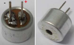
Determining the polarity of Condenser Mic:
MIC has two terminals one is positive and another is negative. Mic polarity can be found using a Multi-Meter. Take the positive probe of Multi-Meter (put the meter in DIODE TESTING mode) and connect it to one terminal of MIC and the negative probe to the other terminal of MIC. If you get the readings on the screen then the terminal of positive (MIC) is at negative terminal of Multi-Meter. Or you can simply find the terminals by looking at it, the negative terminal has two or three soldering lines, connected to the metal case of the mic. This connectivity, from negative terminal to its metal case can also be tested using continuity tester, to find out the negative terminal.
Components Required:
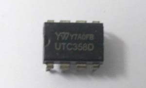
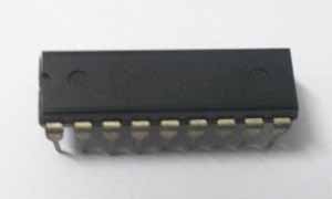
Op-amp LM358 and, LM3914 (10 bit comparator), and a MIC (see above)
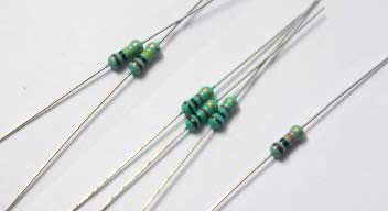
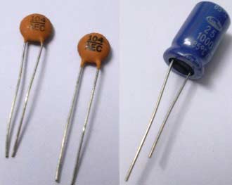
100KΩ resistor (2 pieces), 1K Ω resistor (3 pieces), 10KΩ resistor, 47KΩ pot,
100nF capacitor (2 pieces), 1000µF capacitor, 10 LEDs,

Breadboard and some connector wires.
Circuit Diagram and Working Explanation:
The circuit diagram of the VU meter is show in below figure,

Working of VU meter Circuit is simple; at first MIC picks up the sound and converts it into voltages levels linear to the intensity of sound. So for a higher sound we will have higher value and lower value for a lower sound. Then these voltages signals are fed to High Pass filter to filter out the noise, then after filtration signals are amplified by Op-amp LM358, and finally these filtered and amplified signals are fed to LM3914, which works as a voltmeter and glows LEDs according to the intensity of sound. Now we will explain each step one by one:
1. Removing noise using High Pass Filter:
MIC is very sensitive to sound and also to environmental noises. If certain measures are not taken the amplifier will amplify noise along with the music, this is undesirable. So, before going to amplifier we are going to filter out the noises using High Pass Filter. This filter here is here is a passive R-C filter (Resistor- Capacitor). It’s easy to design and consists of a single resistor and single capacitor.
Since we are measuring the audio range, the filter must be designed accurately. The high pass filter cutoff frequency must be kept in mind while designing the circuit. A high pass filter allows signals of high frequency, passed from input to output, in other words it only allows passing of signals which have higher frequency than the filter prescribed frequency (cut off frequency). A high pass filter is shown in the circuit.
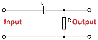
Human ear can pick frequencies from 2-2Khz. So we will design a High Pass filter with cutoff frequency in the range 10-20Hz.
The Cut Off frequency of a high pass filter can be found by formula,
F = 1/ (2πRC)
With this formula we can find the R and C value for a chosen cut off frequency. Here we need a cutoff frequency between 10-20 Hz.
Now for values or R =100KΩ, C = 100nF, we will have Cut Off frequency around 16Hz, which only allows signal of frequency higher than 16Hz, to be appeared at the output. These resistor and capacitor values are not compulsory one can play with the equation for better accuracy or for ease of selection.
2. Amplification of sound signals:
After removing the noise element, signals are fed to Op-amp LM358 for amplification. The OP_AMP stands for “Operation Amplifier”. This is designated by the symbol of triangle with three IO (Input Output) pins. We are not going to discuss about this in detail here. You can go through LM358 circuits for more detail. Here, we are going to use the op-amp as a negative feedback amplifier to amplify the low magnitude signal from MIC and bring them to a level where they can be picked by the LM3914.
A typical op-amp in negative feedback connection is shown in below figure.
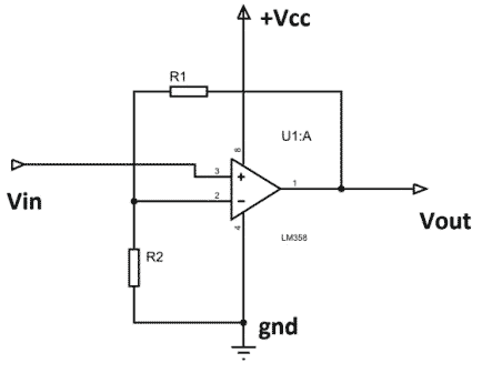
The formula for output voltage is,
Vout = Vin ((R1+R2)/R2). With this formula we can choose the gain of the amplifier.
With the MIC signals at µVolts, we cannot feed it directly to voltmeter for reading, as it will not be practically possible for the voltmeter to pick these low voltages. With the op-amp having a gain of 100, we can amplify the signals from MIC, and further feed it to the Voltmeter.
3. Visual representation of sound levels using LEDs:
So now we have the filtered and amplified audio signal. This filtered amplified audio signal from op-amp, is given to LM3914 chip LED voltmeter for measuring the strength of the audio signal. LM3914 is a chip which drives 10 LED based on intensity of sound/voltage. The IC provides decimal outputs in the form of LED lighting based on the value of input voltage. The maximum measuring input voltage varies depending on reference voltage and supply voltage. This single chip device can be adjusted in a way, from which we can provide visual representation to the analog value of op-amp.
LM3914 chip has many features and it can be modified to a battery protection circuit and Ammeter circuit. But here we only discuss the features which help us in construction of VOLTMETER.
LM3914 is a 10stage voltmeter that means it shows variations in 10 bit mode. The chip senses the measuring input voltage as a parameter and compares it with reference. Say we choose a reference of “V”, now whenever the measuring input voltage rises by “V/10”, we have a LED of higher value glowing. Like if we gave “V/10”, LED1 will glow, if we gave “2V/10” LED2 will glow, if we gave “8V/10”, LED8 will glow. So greater the music volume, more the visual LED representation (more LED glows).
LM3914 IC in the Circuit:
The internal circuit of LM3914 is shown below. LM3914 is basically a combination of 10 comparators. Each comparator is an op-amp, with gaining reference voltage at its negative terminal.
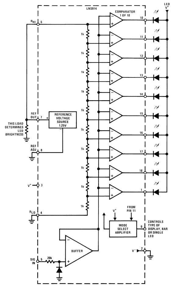
As discussed reference value should be chosen, based on maximum measuring value. The output of OP_AMP will be from 0-4V at max. So we need to choose reference voltage of LM3914 as 4V.
The reference voltage is chosen by two resistors that are connected at RefADJ pin of LM3914 as shown in below figure. The formula regarding Reference Voltage is also given in the figure below (taken from its datasheet),
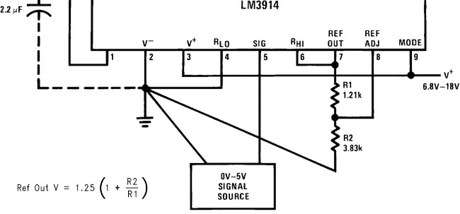
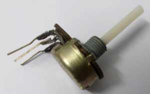
Now, there is a problem with resistance division based voltage reference, that it is somewhat dependent on supply voltage. So we have replaced the constant resistance R2 with a 47KΩ pot as shown in circuit diagram. With the pot in place, we can adjust the reference, depending on convenience.
With a reference of 4V, every time there is an increment of 0.4V according to the sound intensity, the LED of high significance glows. The measuring level for LED goes as,
+0.4V, +0.8V, +1.2V, +1.6V, +2.0V, +2.4V, +2.8V, +3.2V, +3.6V, +4.0V.
So in Nutshell, when there is sound, the MIC generates voltages representing the magnitude of these sound waves, these signals from MIC are filtered by R-C filter. The filtered signals are fed to op-amp LM358 for amplification. These filtered and amplified MIC signals are given to the voltmeter LM3914. The LM3914 comparator voltmeter glow the LEDs according to the strength to the given signal. Hence we have sound measuring instrument, and so VOLUME METER.
Comments
This circuit is not working to me ... Can u explain to me why the electronic scheme is differenr from whar tou have done?
Circuit is perfectly tested, please clear your question.
this config op-amp can ampli from 3.5 mm jack source? i want use audio jack instead of mic
simply replace the mic with 3.5mm jack. remove mic, connect + terminal of jack where the mic + was. replace the ground too.
Instead of the 10-bit comparator, can I use a 8-bot comparator?
If 5k resistance is placed in the place of LEDs, whether output pin voltage will change to 0V from 5V to connect to TTL logic?
Where u connected that 1000mF capacitor
The part's list says that two 0.1u Capacitors and one 1000u Capacitors are required. That is what it appears is on the video. But the schematic states three 0.1u Capacitors. Please clarify.
Connect it across the power supply, it is not necessary and can be omitted.
Hello! Does anyone here have a schematic for the prototype of this circuit on proteus ? I need to complete this project on a pcb and need a schematic...
Sorry if this is a dumb question, but how is the potentiometer connected?
what was the mic used? what should i tell the shopkeeper to give me? what should i search online for?
p.s. I know its a dumb question but ur help will be appreciated
what is the purpose of the potentiometer?
Hello! Instead of microphone, can I use DC motor with potentiometer?
Hai sir, where did u place the 1000uf capacitor. In the circuit diagram there is only three 0.1uf. Is this circuit diagram is correct or where I want to put the 1000uf capa. Give a clear picture.. Plzz respond sir..ASAP.. I Have taken this project as our mini project in college
hello everyone
im here for my enstrumation project. How many volts should the power supply be? thanks for your answer

looking to learn more about electronics