I am building a voltage divider from the B+ supply to run a LED indicator that the Standby switch is closed/HT fuse is not blown/amp should be active/It also acts as a bleeder to bleed the large filter caps when the amp is powered off. Some people may call it an idiot light.
The question I have is about the current devloped across the LED resistor and the how that current interacts with the divider.
So the plan is: Vsource is 350Vdc divided by a 1 megOhm and a 22kOhm providing about 7.5Vdc for the LED circuit, which is just a 470 Ohm resistor feeding the 10mm Blue superbright LED. The LED will have 10 mA of current. So how does the current not interfere with the divider? Or if it is where is the current being supplied from...the lower 22kR, the 1 MegR or all three resistors?
In reply to Generally LEDs are not used by Sourav Gupta
This is not a pilot light. The power switch has the power light indicator built into it and is supplied by the mains before the Power Transformer. I am building a light circuit with an LED that indicates the B+ voltage is engaged and energized when the standby switch is closed. It is multifunctional. It indicates the B+ is energized, provides feedback to the user that it is energized, by default idicates the B+ fuse is not blown. Further when the power is shut off the LED will coninue to luminate in a deteriorating manner while the filter caps discharge to a safe voltage level and help maintain a longer lasting charge balanced cap.
I just want to know how the current interacts with the Voltage divider, is the current supplied by the bottom 22kR alone or is it parallel with the LED resistor or is the entire voltage divider involved? If the latter is the case then I would like to know how so I can have a full understanding of how it affects the whole.

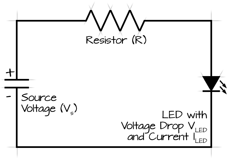
Vs for the divider is B+ approx 350Vdc, Vs for the LED is the Junction of R1(1meg) and R2(22k) approx 7.5Vdc. The LED has a forward voltage of 2.75 Vf, resistor is 390 ohms. So what happens with regard to current when you use the divider to supply the LED voltage.

There is a problem in your circuit. I am explaining why...
Using those value the current flowing through the resistor is 342.5uA. as per kcl what is entering the same current is leaving.
Now, If I change the value of R1, the current gets increased if the R1 decreases. More the current the higher wattage will increase. For running a LED you need atleast 1-2mA of current. Simply put the LED in place of R2 and choose the R1 accroding to it. Do not need to add any divider circuit.


Sourav Gupta
Joined February 12, 2018 696Monday at 02:11 PM
Generally LEDs are not used and neon pilot lamp are used from 6.3V tap of PT. It will be good to do so because, unecessary current drawing from the B+ line could produce hum or noise across the Tubes, it is largely dependent on the wiring as well.
Why you are not using a pilot lamp?