
Smoke Detectors are very useful in detecting smoke or fire in buildings, and so are the important safety parameters. In this DIY session, we are going to build a Smoke Detector Circuit which not only sense the smoke in the air but also reads and displays the level of Smoke in the Air in PPM (parts per million). This circuit triggers the Buzzer when Smoke level becomes higher than 1000 ppm, this threshold value can be changed in the Code according to the requirement. This circuit mainly uses MQ2 Smoke/Gas sensor and Arduino to detect and calculate the level of smoke. MQ2 gas sensor is also sensible to LPG, Alcohol, and Methane etc.
This Smoke Detector can be easily built on Bread Board or Dot Board but we have decided to build this as an Arduino Shield on PCB. We have used EasyEDA online PCB simulator and designer to build this Smoke Detector Shield for Arduino. We have explained the whole process in this Article and also provided PCB layout for this Arduino Shield so that you can also order this Shield if you need.
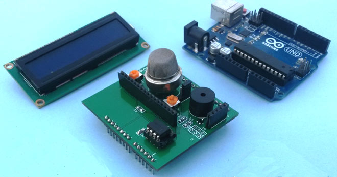
Components Required:
- Arduino UNO
- Smoke Detector Arduino Shield (Self Designed)
- Power Supply
Components for Smoke Detector Arduino Shield:
- Smoke Sensor (MQ2)
- Resistors (10K and 1K)
- Buzzer
- 16x2 LCD
- 10k POT
- LED
- LM358
- Burg strips
Designing Smoke Detector Shield for Arduino:
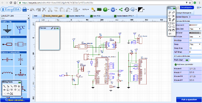
For designing Smoke Detector Shield for Arduino we have used EasyEDA, in which first we have designed a Schematic and then converted that into the PCB layout by Auto Routing feature of EasyEDA.
To design circuit and PCB for this Smoke Detector Shield, we chose EasyEDA which is a free online tool and one stop solution for developing your electronics projects with ease. It offers schematic capture, spice simulation, PCB design for free and also offers high quality but low price Customized PCB service. There are a large number of component libraries in its editor, so you can easily and quickly find your desired parts. Check here the complete tutorial on How to use Easy EDA for making Schematics, PCB layouts, Simulating the Circuits etc.
We have made the Circuit and PCB design of this Smoke Detector Shield public, so you can just follow the link to access the Circuit Diagram and PCB layouts:
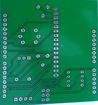
Below is the Snapshot of Top layer of PCB layout from EasyEDA, you can view any Layer (Top, Bottom, Topsilk, bottomsilk etc) of the PCB by selecting the layer form the ‘Layers’ Window.

If you find any problem in using EasyEDA, then check out our previously developed 100 watt inverter circuit, where we have explained the process step by step.
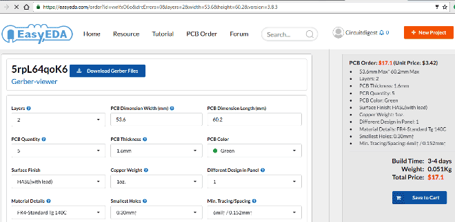
Ordering the PCB online:
After completing the design of PCB, you can click the icon of Fabrication output, which will take you on the PCB order page. Here you can view your PCB in Gerber Viewer or download Gerber files of your PCB and send them to any manufacturer, it’s also a lot easier (and cheaper) to order it directly in EasyEDA. Here you can select the number of PCBs you want to order, how many copper layers you need, the PCB thickness, copper weight, and even the PCB color. After you have selected all of the options, click “Save to Cart” and complete your order, to receive your PCBs within few days.
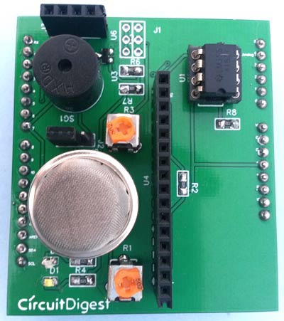
After few days of ordering the PCB, we got our Smoke Detector Arduino Shield PCB, and we found the PCBs in nice packaging and the quality of PCB is quite impressive.
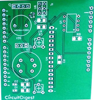
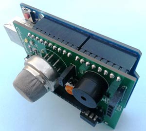
After getting the PCBs, we have mounted and soldered all the required components and burg strips over the PCB, you can have a final look here:
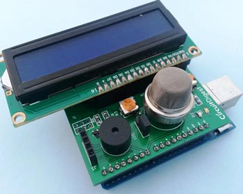
Now we just need to attach LCD to the Shield and place this Smoke Detector Shield over the Arduino. Align the Pins of this Shield with the Arduino and firmly press it over the Arduino. Now just upload the code to the Arduino and power on circuit and you are done! Your Smoke Detector is ready to test. Check the Video at the end for demonstration.
Circuit Explanation:
In this Smoke Detector Circuit with Arduino, we have used a MQ2 Gas Sensor to detect preset smoke in the air. A 16x2 LCD is used for displaying the PPM value of Smoke. And an LM358 IC for converting smoke sensor output into digital form (this function is optional). A buzzer is placed as an alarm which gets triggered when smoke level goes beyond 1000 PPM.
Circuit connections for this project are very simple, we have a Comparator Circuit for comparing output voltage of smoke sensor with preset voltage (output connected at pin D7). Also smoke sensor output is connected at an analog pin of Arduino (A0). Buzzer is connected at Pin D9. And LCD connections are same as Arduino LCD examples that are available in Arduino IDE (12, 11, 5, 4, 3, 2). Remaining connections are shown in the circuit diagram.

Note: In the circuit we need to short all the three pin of J2 header to calculate PPM of smoke.
Programming Explanation:
Program of this project is little difficult to make. User needs to read MQ2 Smoke Sensor datasheet very carefully to understand the calculations for this project. In this we have to read slop or curve of smoke concentration in air with respect to clean air. After reading datasheet, we get some values that we will need in the Code to calculate ppm of smoke in air. Here mostly we need curve values (we take two points from the curve), sensor resistance (will be calculated in code), clean air constant (9.83) and Load Resistance (I used 10K). We can find curve values from the datasheet and we can put load resistance 5k-54k and then we will calculate sensor resistance by these value and smoke samples.
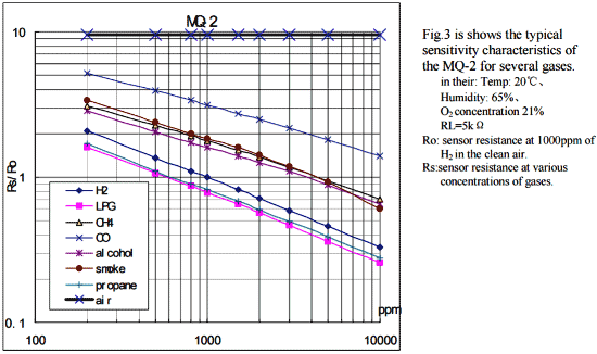
Take two points from the curve and take log of them like point one: (lg200, lg3.4)=(2.3,0.53) and point two: (lg10000,lg0.63)=(4,-0.20). Then find slope of the curve using Formula: (y2-y1)/(x2-x1), then take one point and slope (-0.44) and use them in the Program (x, y, slope). Further check the Code below to understand the Calculation.
First we need to include header file for LCD and define pins for the same. Then define curve values and load resistance.
#include <LiquidCrystal.h>
LiquidCrystal lcd(12, 11, 5, 4, 3, 2);
#define buzzer 9
#define sensor A0
#define load_Res 10
#define air_factor 9.83

float SmokeCurve[3] ={2.3,0.53,-0.44};

float Res=0;
Now in void setup(), we need to Calibrate the module by using SensorCalibration function:
void setup()
{
  lcd.begin(16,2);
  lcd.print("Calibrating.....");
  Res = SensorCalibration();
  lcd.print("Calibration done.");
  lcd.setCursor(0,1);
  lcd.print("Res=");
  lcd.print(Res);
  lcd.print("kohm");
  delay(2000);
  lcd.clear();
  pinMode(buzzer, OUTPUT);
}
float SensorCalibration()
{
int i;
float val=0;
val=resistance(50,500);
val = val/air_factor;
return val;
}Then in void loop() function, we have calculated the PPM of smoke by using resistance Function:
void loop()
{
lcd.setCursor(0,0);
lcd.print("SMOKE:");
float res=resistance(5,50);
res/=Res;
int result=pow(10,(((log(res)-SmokeCurve[1])/SmokeCurve[2]) + SmokeCurve[0]));
lcd.print(result);
lcd.print( " ppm ");
if(result>1000)
{
digitalWrite(buzzer, HIGH);
delay(2000);
}
else
digitalWrite(buzzer, LOW);
delay(500);
}float resistance(int samples, int interval)
{
int i;
float res=0;
for (i=0;i<samples;i++)
{
int adc_value=analogRead(sensor);
res+=((float)load_Res*(1023-adc_value)/adc_value);
delay(interval);
}
res/=samples;
return res;
}Note: Before calibrating the module, leave the project for 10 minute in clean air with power On and then start the calibration. This calibration process will take at least 25 seconds.
Find the complete Code and Demonstration Video below.
So here we have built the Smoke Detector Circuit using Arduino, which also calculates and displays the level of the Smoke in PPM. For this Project, we have developed our own Smoke detector Arduino Shield using EasyEDA PCB designing services, and made those PCB layouts Public so that anyone can use them to order this Smoke Detector Shield.
Complete Project Code
#include <LiquidCrystal.h>
LiquidCrystal lcd(12, 11, 5, 4, 3, 2);
#define buzzer 9
#define sensor A0
#define load_Res 10
#define air_factor 9.83
float SmokeCurve[3] ={2.3,0.53,-0.44}; // (x, y, slope) x,y coordinate of one point and the slope between two points
float Res=0;
void setup()
{
lcd.begin(16,2);
lcd.print("Calibrating.....");
Res = SensorCalibration();
lcd.print("Calibration done.");
lcd.setCursor(0,1);
lcd.print("Res=");
lcd.print(Res);
lcd.print("kohm");
delay(2000);
lcd.clear();
pinMode(buzzer, OUTPUT);
}
void loop()
{
lcd.setCursor(0,0);
lcd.print("SMOKE:");
float res=resistance(5,50);
res/=Res;
int result=pow(10,(((log(res)-SmokeCurve[1])/SmokeCurve[2]) + SmokeCurve[0]));
lcd.print(result);
lcd.print( " ppm ");
if(result>1000)
{
digitalWrite(buzzer, HIGH);
delay(2000);
}
else
digitalWrite(buzzer, LOW);
delay(500);
}
float resistance(int samples, int interval)
{
int i;
float res=0;
for (i=0;i<samples;i++)
{
int adc_value=analogRead(sensor);
res+=((float)load_Res*(1023-adc_value)/adc_value);
delay(interval);
}
res/=samples;
return res;
}
float SensorCalibration()
{
  int i;
  float val=0;
  val=resistance(50,500);
  val = val/air_factor;
  return val;
}
Comments
This is the custom made shield and we have provided all the links about PCB layout, Gerber viewer, circuit etc with the list of components.
can you give us the full schematic diagram?
Can you give us the smoke shield circuit diagram?
can I use this code for hydrogen sensor?
calibration value is same or not for hydrogen gass?
Does the coding works for a stock MQ-2 sensors or it only works for this custom PCB?
Sir how I can make this project by using 8051 plz give source code for 8051
Sir please can you show me the process involve and alternative components to get that work done if some components are not found in my area..? How can I also do for 3 sensors to keep in 3 different rooms such that when smokers detected the LCD tells the room the smoke is sensed. Please sir help me.
sir can i build this without LM358 and whats the new connection.?
I have to admit that early on I was frustrated when trying to perform these projects because it was rare that I could get them to work. As my knowledge of Arduino increases, these projects are easier to get working. Usually it's a minor matter of small tweaks here and there if at all to get them running perfectly.
The projects here are VERY well done. Among the best.
Thanks for presenting them. Have you ever considered capitalizing on these projects....such as offering to sell the PCBs you create? I, for example, would not hesitate to order the PCB from this project for $10.00. Wouldn't that be profitable? Maybe you tried and people were not willing to make even the smallest investment?
Hi,
is it possible to use yor shield with MQ7 Carbonmonoxide Sensor?
Not with the same code of course.
Kind regards
All MQ sensors have the same pinouts so you can replace directly. Just make sure the Vcc, Gnd and Analog pins are connected properly. Since the project is done on EasyEDA it would be easy for you to use the link to make the changes
how can i get esp8266 port
can i use the ppm calculation for carbon monoxide using mq9 sensor?

please list the components i need for this design. of this project and where i can get them or i check it in my area ..i will be very happy to do refers to friends..
Thanks