

RFID stands for Radio Frequency Identification, it’s a very simple and inexpensive piece of technology that can be used to make applications such as RFID Based Door Lock, RFID based Attendance System. If you search online for RFID Based Projects, you will find many projects that are associated with security and tagging which might make this interesting module appear boring.
To change the trend, we thought of building an RFID Based IoT Enabled Event Management System that not only monitors the entry log but with the help of IoT technology but can also send the Log and Entry data directly to a dedicated server that can handle all the authentication, authorization, and management making the whole process seamless. So let's get right onto it.
Components Required to Build RFID Based Event Management System
- EM18 RFID Reader
- RFID Cards
- NodeMCU
- 16*2 Alphanumeric LCD
- I2C module for LCD
- Breadboard
- Connecting Wires
The EM18 RFID Reader Module

The above image shows an EM18 RFID Reader module alongside the RFID Card. RFID technology is nothing new, but it’s a piece of technology where digital data is encoded in RFID tags and can be decoded by an RFID reader using radio waves. RFID is similar to barcoding in which data from a tag is decoded by a device. RFID technology is used in various applications like Security system, Employee attendance system, RFID Door Lock, RFID Based Voting Machine, Toll Collection System, etc.
EM18 Reader is a module that can read the ID information stored in the RFID tags. The RFID stickers store a 12 digit unique number which can be decoded by an EM18 reader module when the tag comes in range with the reader. This module operates at a frequency of 125 kHz, has a built-in antenna, and is operated using a 5 volt DC power supply. It gives a serial data output and has a range of 8-12 cm. The serial communication parameters are 8 data bits, 1 stop bit, and 9600 baud rate.
This is a very useful module and comes with some interesting features. It has a wide operating voltage range, can operate from +4.5V to 5.5V DC, consumes just 50mA of current while operating, so it can be powered from a battery. Apart from that, it has a 125Khz operating frequency which makes it compatible with various types of RFID cards. With the help of a built-in antenna, it can read a distance of 8cm to 12cm. It has an operating temperature of 0-80 °C which makes it suitable for application in harsh environments.
Pin Description of EM18 Rfid Reader Module:
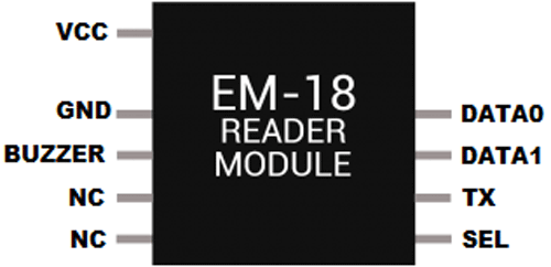
The pinout of the EM18 RFID Scanner module with description is shown below.
VCC: 4.5- 5V DC voltage input
GND: Ground pin
Buzzer: Buzzer or LED pin
TX: Serial data Transmitter pin of EM18 for RS232 (Output)
SEL: This must be HIGH for using RS232 (LOW if using WEIGAND)
Data 0: WEIGAND data 0
Data 1: WEIGAND data 1
Circuit Diagram of RFID Based Event Management System
The complete circuit diagram for the RFID Based IoT Enabled Event Management System is shown below.

As you can see from the circuit diagram, we have connected the EM-18 module with the NodeMCU with the help of the UART. We have provided power to the board from the Node MCU board as the EM-18 Reader module draws 50mA peak current, the onboard power supply is sufficient enough to drive the module. Similarly, we have connected the I2C LCD with the help of the I2C pins of the NodeMCU and we are also powering the LCD from the NodeMCU module.
Setting Up ThingSpeak Account for RFID Based Event Management System
After successful completion of hardware as per the above circuit diagram, we have to configure the ThingSpeak IoT platform, where we will store all of our data. Here, we are using ThingSpeak to store the user's information. We will then display the Data to GUI. For creating an account in Thingspeak, follow the steps below.
Sign up for a ThingSpeak Account:
First, go to https://thingspeak.com/ and create a new free Mathworks account if you don’t have a Mathworks account.
Sign in to ThingSpeak:
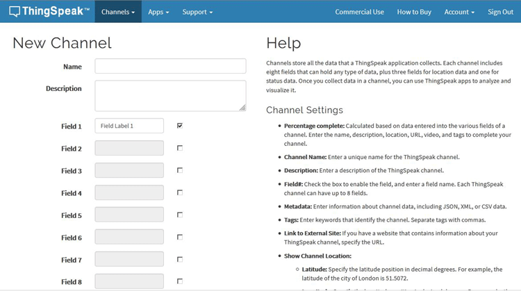
Sign in to ThingSpeak using your credentials and click on “New Channel”. Now, fill up the details of the project like Name, Field names, etc. Here, we have to create four field names such as Temperature, Voltage, etc. Thereafter, click on “Save channel”.
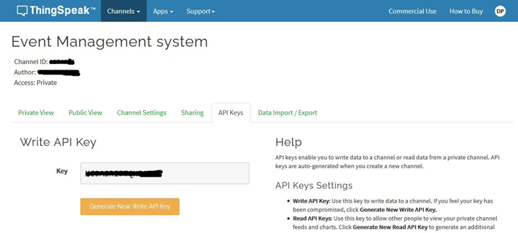
Record the Credentials:
Select the created channel and record the following credentials.
- Channel ID, which is at the top of the channel view.
- Write API key, which can be found on the API Keys tab of your channel view.
Once we have completed the setup and we have the essential credentials, we can move onto the coding part.
Arduino Code for RFID Based Event Management System
After successfully setting up a ThingSpeak account and doing the hardware setup as per the circuit diagram, it’s time to program the NodeMCU Board. But if you are uploading code to NodeMCU Board for the first time, then follow the steps given below.
Adding Support for NodeMCU in Arduino IDE:
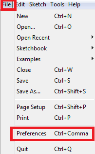
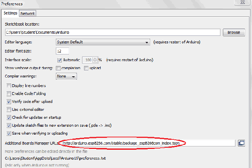
Open Arduino IDE, then go to File–>Preferences–>Settings.
Enter https://arduino.esp8266.com/stable/package_esp8266com_index.json in the ‘Additional Board Manager URL’ field and click ‘Ok’.
Now, go to Tools > Board > Boards Manager. In the Boards Manager window, Type ESP8266 in the search box, select the latest version, and click on install.
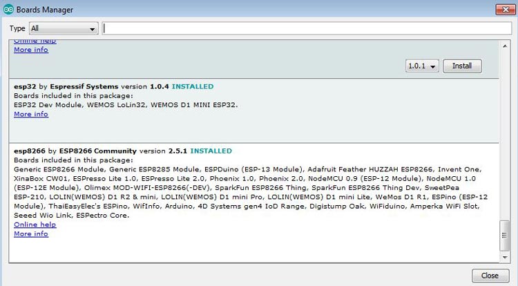
After the installation is complete, go to Tools ->Board -> and select NodeMCU 1.0(ESP-12E Module). Now you can program NodeMCU with Arduino IDE.
After the above setup for programming NodeMCU, we have to upload the complete code to ESP8266 NodeMCU.
Getting the Unique RFID Code from RFID Tag:
Before programming the NodeMCU, we need to find out the unique 12 digit RFID code. As we discussed before, RFID tags contain a 12 digit unique code and it can be decoded by using an RFID reader. When we swipe the RFID tag near the Reader, the Reader will give us a unique code via the serial port on getting connected to NodeMCU. For that, we need to set up a small piece of code, and once we get the codes for all our modules, we will need to keep them safe for later use.
After successfully uploading the small code given below, open the serial monitor, and set the baud rate to 9600. Then swipe the card near the Reader and you will see the 12 digit code displayed on the serial monitor. Do this process for all the used RFID tags and note them down for future references.
Arduino Program to get Unique 12 Digit RFID Tag Code:
int count = 0;
char card_no[12];
void setup()
{
   Serial.begin(9600);
}
void loop()
{
   if(Serial.available())
   {
      count = 0;
      while(Serial.available() && count < 12)
      {
         card_no[count] = Serial.read();
         count++;
         delay(5);
      }
      Serial.print(card_no);
   }
}
Final Code for Arduino Based Event Management Project:
We start the code by including all the required library files. We have used the ThingSpeak.h library to communicate with the ThingSpeak platform. You can add this library with the help of the board manager method. As we are using a 16x2 I2C based LCD, we have to include the “LiquidCrystal_I2C.h” and “wire. h” libraries. We also need to include the time library that will help us to get our current timestamp.
#include "ThingSpeak.h"
#include <ESP8266WiFi.h>
#include<LiquidCrystal_I2C.h>
#include<Wire.h>
#include <time.h>
Next, we initialize our LCD with the help of the function given here.
LiquidCrystal_I2C lcd(0x3f, 16, 2);
Now, we define all the necessary network credentials i.e. SSID and Password. These are required to connect the NodeMCU with the internet. Then we define all the credentials for the ThingSpeak account such as the channel number and write API which was recorded earlier. Make sure, you have edited your credentials in place of these variables.
unsigned long ch_no = 123456
const char * write_api = "MCxxxxxxx";
char ssid[] = "admin";
char pass[] = "12345678";
inside setup(), we start by enabling the serial monitor. Next, we get the current timestamp. Thereafter, we use the wire function to initialize the LCD.
Serial.begin(9600);
configTime(11 * 1800, 0, "pool.ntp.org", "time.nist.gov");
Wire.begin(D2, D1);
lcd.begin(16, 2);
lcd.init();
To connect nodeMCU to the internet, the WiFi.begin function was called and the network SSID and password were passed as its arguments. After that, we checked if Wi-Fi is connected or not using WiFi.status() function, and upon successful connection, a message was shown on the LCD was stating “WiFi connected”.
WiFi.begin(ssid, pass);
  while (WiFi.status() != WL_CONNECTED)
  {
    delay(500);
    Serial.print(".");
  }
  Serial.println("WiFi connected");
  Serial.println(WiFi.localIP());
  lcd.setCursor(0, 1);
  lcd.print("WiFi connected");
Inside while(1) loop, we count the total no. of visitors displayed on LCD using command lcd.print as shown below.
lcd.setCursor(0, 0);
lcd.print("No. of Vis:" + String(vis_count));
To get the current timestamp, time() was used and the output was saved in a character array as shown below.
time_t now = time(nullptr);
str = ctime(&now);
Here, the unique 12 digit codes of the RFID tags are decoded and stored in an array. Then the elements of the array will be matched with the Stored Tag numbers in the memory to get the visitor’s details. Remember the Tag details we saved earlier.
if (Serial.available())
  {
    count = 0;
    while (Serial.available() && count < 12)
    {
      input[count] = Serial.read();
      count++;
      delay(5);
    }
Here, we compare the received array with the stored tag codes. If the code matches with any saved card details, then this condition is executed and the visitor information is displayed on LCD.
if (count == 12)
    {
      if ((strncmp(input, "0B00284F9AF6", 12) == 0) && (a == 0))
      {
        lcd.setCursor(0, 1);
        lcd.print("Welcome Debasis         ");
        vis_count++;
        a = 1;
        delay(2000);
        lcd.clear();
        senddata("Debasis");
      }
}
Senddata() function is used to send the visitor data to ThingSpeak cloud. From ThingSpeak, we can download this data later in excel format to see the recorded details such as Visitor Name and Time of Entry, etc.
void senddata(String input)
{
  ThingSpeak.setField(1,input);
  ThingSpeak.setField(2, str);
  ThingSpeak.writeFields(ch_no, write_api);
}
This marks the end of our coding section, now we can move onto the testing part.

Working of RFID and NodeMCU Based Event Management System
To test the project, we turned on the NodeMcu and made sure that the WiFi network is available, to which the NodeMCU will get connected.
After this, a message will be displayed on the LCD showing “WiFi connected”. If it is not showing then try to check your network availability and connection.
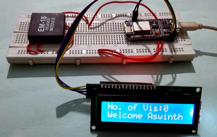
After that, we swipe our card on the RFID reader upon which you will be prompted with a Welcome Message on the LCD as shown below. We repeat this process for all the RFID cards until we are satisfied with the results. The image given below shows one such case.
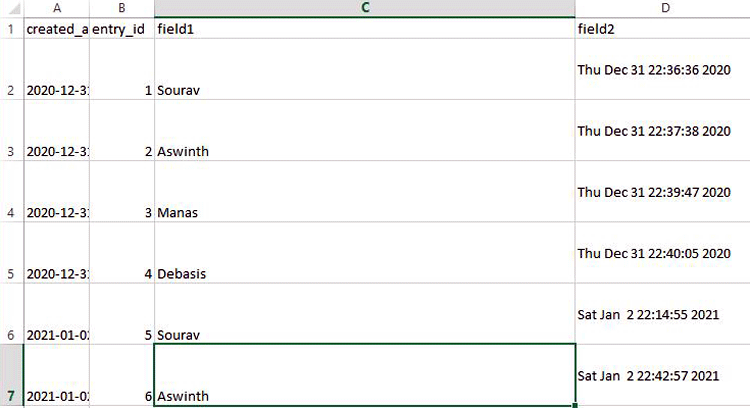
Finally, to download this data from the ThingSpeak cloud, Sign in to ThingSpeak and Click on the “Data Import/Export” Tab. Under the Export menu, choose the correct Time Zone and click Download. It will download the Excel sheet in .csv format which looks like below.
This marks the end of this article. I hope you enjoyed the article and learned something new. If you have any questions regarding the article, do not hesitate to put a comment below.
Complete Project Code
#include "ThingSpeak.h"
#include <ESP8266WiFi.h>
#include<LiquidCrystal_I2C.h>
#include<Wire.h>
#include <time.h>
LiquidCrystal_I2C lcd(0x3f, 16, 2);
unsigned long ch_no = 124555;//Replace with ThingSpeak Channel number
const char * write_api = "cvxxx";//Replace with ThingSpeak write API
char ssid[] = "admin";
char pass[] = "12345678";
int count = 0;
int vis_count = 0;
char input[12];
int a = 0, b = 0, c = 0, d = 0, e = 0;
WiFiClient  client;
const char *str;
void setup()
{
  Serial.begin(9600);
  configTime(11 * 1800, 0, "pool.ntp.org", "time.nist.gov");
  Wire.begin(D2, D1);
  lcd.begin(16, 2);
  lcd.init();
  lcd.backlight();
  lcd.setCursor(0, 0);
  lcd.print("   WELCOME TO       ");
  lcd.setCursor(0, 1);
  lcd.print(" CIRCUIT DIGEST      ");
  delay(2000);
  lcd.clear();
  WiFi.begin(ssid, pass);
  while (WiFi.status() != WL_CONNECTED)
  {
    delay(500);
    Serial.print(".");
  }
  Serial.println("WiFi connected");
  Serial.println(WiFi.localIP());
  lcd.setCursor(0, 1);
  lcd.print("WiFi connected            ");
  delay(2000);
  lcd.clear();
  ThingSpeak.begin(client);
}
void loop()
{
  lcd.setCursor(0, 0);
  lcd.print("No. of Vis:" + String(vis_count));
  time_t now = time(nullptr);
  str = ctime(&now);
  if (Serial.available())
  {
    count = 0;
    while (Serial.available() && count < 12)
    {
      input[count] = Serial.read();
      count++;
      delay(5);
    }
    if (count == 12)
    {
      if ((strncmp(input, "0B00284F9AF6", 12) == 0) && (a == 0))
      {
        lcd.setCursor(0, 1);
        lcd.print("Welcome Debasis         ");
        vis_count++;
        a = 1;
        delay(2000);
        lcd.clear();
        senddata("Debasis");
      }
      else if ((strncmp(input, "0B002854EB9C", 12) == 0) && (b == 0))
      {
        lcd.setCursor(0, 1);
        lcd.print("Welcome Manas           ");
        b = 1;
        vis_count++;
        delay(2000);
        lcd.clear();
        senddata("Manas");
      }
      else if ((strncmp(input, "0B0029516C1F", 12) == 0) && (c == 0))
      {
        lcd.setCursor(0, 1);
        lcd.print("Welcome Aswinth          ");
        c = 1;
        vis_count++;
        delay(2000);
        lcd.clear();
        senddata("Aswinth");
      }
      else if ((strncmp(input, "0B00292F5E53", 12) == 0) && (d == 0))
      {
        lcd.setCursor(0, 1);
        lcd.print("Welcome Sourav            ");
        d = 1;
        vis_count++;
        delay(2000);
        lcd.clear();
        senddata("Sourav");
      }
      else if ((strncmp(input, "0B00283E6479", 12) == 0) && (e == 0))
      {
        lcd.setCursor(0, 1);
        lcd.print("Welcome Rakesh            ");
        e = 1;
        vis_count++;
        delay(2000);
        lcd.clear();
        senddata("Rakesh");
      }
      else
      {
        lcd.setCursor(0, 1);
        lcd.print("Welcome Back!!!          ");
        delay(2000);
        lcd.clear();
      }
    }
  }
}
void senddata(String input)
{
  ThingSpeak.setField(1,input);
  ThingSpeak.setField(2, str);
  ThingSpeak.writeFields(ch_no, write_api);
}Comments
WIFI Not connecting, Can anyone help?
what are its application and , its strength

There are many errors in the code.
First of all there is an error of D2,D1.
Wifi is not connecting to Esp8266 een after adding WiFi.mode(WIFI_STA);