This is a very interresting circuit and I've been looking for something like that for a while. Got all the components, followed the shcematic and built the breadboard for testing.
Unfortunately, it does not work. I can get the LED to blink at various rate using the variable resistance but the AC circuit refuses to work. I use 5vdc as input to the 555 timer (output is 2.9vdc into the optocoupler). since I am in Canada, it's 120VAC instead of 220 but I dont think it makes a difference. Also, I am using a LED house bulb instead of incandescent. Tried both to no avail. The TRIAC is a bt136 and tested OK.
Any ideas....
Thanks for the help and insights
Robert

Good morning and thanks for the quick reply.
The 555 part of the circuit works very well and the LED flashes properly when turning the variable resistor. However, I can't get the AC bulb to flash...

so the problem must be in the TRIAC and its driving section, please try the circuit given in the below link(Just use the TRIAC section).
circuitdigest.com/fullimage?i=circuitdiagram_mic/AC-Fan-Regulator-Control-Circuit.png
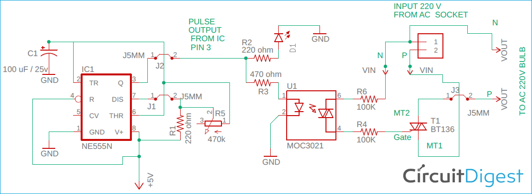
Thanks for the suggestions. The circuit I am using is a project from this site (as the title suggest) and here is the cirduit diagram :
As stated, it works well up to the LED. After that , nothing. I followed everything to exact specs and can't get the light bulb to blink.

Thanks for the advice, will try it tonight and report back
I had to put this on hold for a while but thanks to all your kind help, the thing is up an running well.
R4 and R6 is 10K 1/2 watt. The rest is as per schematic. Any other resistance (1k and shorting R6) would blow up.

It is a simple circuit which consists of a 555 Timer IC to generate PWM pulse, this pulse is then used to control the blinking interval of the AC bulb through a TRIAC circuit which drives the AC bulb.

Debashis Das
Joined December 02, 2019 117Monday at 10:02 PM
Hi Robert, In the circuit diagram there is an LED D1, first check that part of the circuit is working or not. if it's not working then the problem is within 555 timer circuit section, please check that section first.