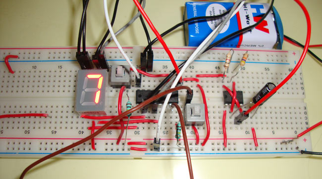
Reaction timer is a game to test how fast you reacts. This game which we have developed using 555 IC is for two players where first player starts the game by pressing start button. As soon as the START button is pressed, 7 segment display starts displaying 0 to 9 numbers in a high speed. Then other player stops the counting by pressing the STOP button. As the frequency of displaying numbers is very high, it is difficult and needs full attention to react on the correct time. Watch the video below to see demonstration of this reaction timer game.
Required Components
555 timer IC
4026 IC
7 segment display
Two- push ON, push OFF button.
Resistors – 100k (2), 1k, 47k
Capacitor 1uF
Circuit Diagram and Explanation
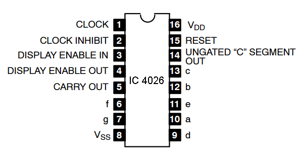
Here we are using 4026 IC, which is a 4000 series CMOS seven-segment counter IC. It is used to display numbers on seven segment displays and increment the number by one, when a clock pulse is applied to its PIN 1. That means more the clock pulse rate, faster the numbers change on 7 segment. Below is the pin diagram and pin description of 4026 IC.
IC 4026 Pin Diagram

IC 4026 Pin Description
|
Pin number |
Name |
Description |
|
1 |
CLK |
Clock in |
|
2 |
CI |
Clock inhibit - when low, clock pulses increment the seven-segment |
|
3 |
DE |
Display enable- chip will be ON when this pin is HIGH, and OFF if it is LOW. |
|
4 |
DEO |
Display enable out - for chaining 4026s |
|
5 |
CO |
The CARRY-OUT (Cout) signal completes one cycle every ten CLOCK INPUT cycles and is used to clock the succeeding decade directly in a multi-decade counting chain |
|
6 |
F |
Connected to ‘f’ of the 7 segment. |
|
7 |
G |
Connected to ‘g’ of the 7 segment. |
|
8 |
VSS |
Ground PIN |
|
9 |
D |
Connected to ‘d’ of the 7 segment. |
|
10 |
A |
Connected to ‘a’ of the 7 segment. |
|
11 |
E |
Connected to ‘e’ of the 7 segment. |
|
12 |
B |
Connected to ‘b’ of the 7 segment. |
|
13 |
C |
Connected to ‘c’ of the 7 segment. |
|
14 |
UCS |
Ungated C-segment - an output for the seven-segment's C input which is not affected by the DE input. This output is high unless the count is 2, when it goes low. |
|
15 |
RST |
Reset PIN, active HIGH. |
|
16 |
VDD |
Power supply PIN |
Pin 2 is used to freeze the display in 7 segment when connected to HIGH, which we have used on STOP button. Pin 15 is used to reset the IC when HIGH and seven segment displays 0, this PIN is used on START/RESET switch. Both the PIN 2 and 15 are active high pins.
PINS 6,7,9,10,11,12,13 are used to connect with the 7segemet display, we have used common cathode seven segment display, in which cathodes, of the all LEDs inside 7 segment, are connected together.
Now the main component of the circuit, 555 timer IC comes into picture. 555 is used here to provide the CLOCK pulse to 4026 IC at PIN 1 so that numbers can be changed in 7 segment. 555 is used in Astable multivibrator mode, and the clock pulse rate can be controlled by the Resistor R1, R2 and the Capacitor. Here we have used approximately 15 pulses/second, i.e. numbers are changing 15 times in a second. If we want to slow down the rate at which the numbers are changing, we can increase the value of capacitor, like you can try using capacitor between 1uf to 10uf, and get the desired speed.
Comments
about logisim for reation timer game
Hello sir ,
this is vijay rathod ,we are doing project on this topic for that we need logisim can you please design logisim for this circuit diagram shown above for this project


Hellow sir i made this projext but its not working cant read the num on seven segme t even i chexked it on proteus help me.plz