

While doing projects using Arduino, we always need to connect Arduino to PC in order to upload the program in it. But sometimes it is very uncomfortable to always connect the board with PC as if it is a robotics project then you always have to move the robot near to labtop to re-program it. This problem can be solved by programming the Arduino wirelessly. So here we are building a circuit to program the Arduino wirelessly using Bluetooth module HC-05.
Components Used:
- Arduino UNO
- HC05 Bluetooth Module
- Perfboard
- Male, Female Headers
- Jumpers
- 1K,2.2K Resistors
- 0.1uF capacitor
- 9V Battery
HC-05 Bluetooth Module
HC05 is basically a Bluetooth module which supports Serial Port Protocol (SPP) and is popularly used in many wireless applications. HC05 can be used to switch between master mode and slave mode and it has a transmission distance of 20-30 metre in free space. We have previously made many Bluetooth projects using HC-05 and other Bluetooth module.
Pin out:
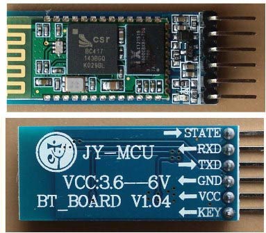
Pin Description:
- +5V: Power supply pin of HC05 which can be given with +5V.
- GND: Ground pin.
- TX: Used as Transmitter pin in UART.
- RX: Used as Receiver pin in UART.
- EN/KEY: Enable pin of HC05. It can be left in floating state or can be connected to 3.3V supply to enable HC05. If it is connected to Ground then module will be disabled. It is also used to make HC05 in AT command mode.
- STATE: Status pin which is LOW in case of not connected to any device and HIGH when connected to any device.
Programming Arduino UNO for AT commands:
First we have to program the Arduino to respond to AT commands through Serial monitor. Program is very simple and attached at the end of this tutorial, here we are explaining the program line by line.
First include the header file for software serial library and define the Transmitter and Receiver pins for Software serial in Arduino, which are pin 3 and 2 in this case.
#include <SoftwareSerial.h>
SoftwareSerial HC05(2,3);
Next, in setup function, define the baud rates for both Hardware serial ports and Software serial ports. Here we have taken them as 9600 and 38400 respectively.
void setup()
{
Serial.begin(9600);
Serial.println("Enter AT commands:");
HC05.begin(38400);
}
In the loop function, there are two conditions- one is when any command is given to HC05 and it writes them at Arduino serial Monitor. Another condition is when any command is given at Arduino serial monitor and it will send them to HC05.
void loop()
{
  if (HC05.available())
    Serial.write(HC05.read());
  if (Serial.available())
    HC05.write(Serial.read());
}
Configuration of HC05 in AT Command Mode:
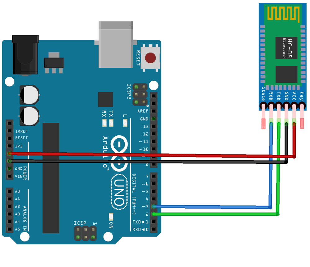
First of all, connect the components as per circuit diagram below. Then follow the steps below to put the module in AT command mode.
To enter in the AT mode of HC05, we need to use the KEY button. First long press the key button until the module LED start blinking at an interval of 2 seconds. If the LED starts blinking in every 2 seconds interval means the module is in command mode. We can now give AT commands to it using the Serial monitor of Arduino IDE.
If the module doesn’t have any key button in it, then we can connect the KEY/EN pin of the module to 3.3 volt pin to switch the module in command mode.
AT commands to configure HC05 for wireless programming:
Once the sketch is uploaded into Arudino, open the serial monitor at 9600 baud rate, select CR+NL, and you should be able to send AT commands to the HC-05.
After successful completion of the above steps, now send the appropriate AT commands to configure the HC05. Send the following AT commands one by one at Arduino serial Monitor and in return it should an OK response. Otherwise, recheck the connections and try it again.
AT
It is the basic Test command of HC05. Every time we transmit AT, it must return OK.
AT+ORGL
This command will restore the default setting of HC05. The default settings are for slave mode, password=1234 and baud rate=38400 bits/sec.
AT+NAME= CIRCUIT DIGEST
This command will set the name of the HC05 module. In my case I have given the name as “CIRCUIT DIGEST”.
AT+ROLE=0
This command will configure the HC05 in slave mode.
AT+POLAR=1,0
This command sets the PIO LEDs drive configurations.
AT+UART=115200,0,0
This will change the baud rate to 115200 with 0 stop bit and 0 parity.
AT+INIT
This will initialize the SPP profile of the module.

Circuit Connection for Arduino Wireless Programming
After successfully sending AT commands to Arduino, just remove all the connections and rebuild it as per the schematics below.

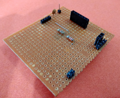
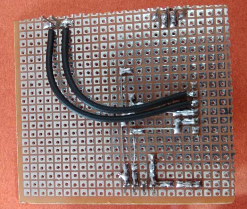
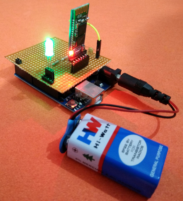
In my case I have soldered it on a perfboard, so that it can be easily fitted with Arduino pins and can work as a Arduino Shield. After the complete soldering, it will look like below:
Then just place this shied on Arduino as per image below, and then connect the Arduino to 9V battery Power supply.

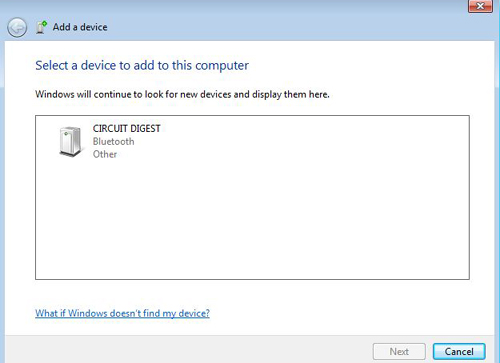
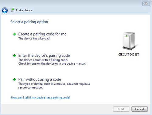
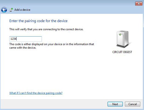
After it, search for Bluetooth setting in your PC, and click on add a Bluetooth Device. This will scan for new devices and in results we shall get our Bluetooth device. Select the device and click Next. Click on “Enter the device pairing code” option. When it asks for pairing code, enter “1234” as your password. Then you will get an acknowledgement for successful device pairing.
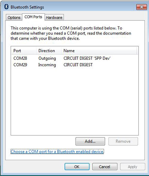
After successful pairing of the device, the next task it to find out the COM port for HC05 Bluetooth module. For this, search for Change Bluetooth Settings, then click on the tab COM Ports. This will show two COM ports, one is for incoming and other for outgoing. We have to write down the outgoing COM port number as we need it further while uploading the program.
The final step is to upload a sample program to Arduino wirelessly to check weather this Arduino Wireless Programming is working perfectly or not. For this, select any Arduino program from Arduino IDE example programs, here I have selected the LED blinking program. Select Arduino UNO in board and then select correct COM port in Port, as shown above. After that click on upload button and it should be successfully uploaded to your Arduino board.
Check the demonstration video below and enjoy the wireless and hasslefree programming!!!
Complete Project Code
#include <SoftwareSerial.h>

SoftwareSerial HC05(2,3);

void setup()

{

Serial.begin(9600);

Serial.println("Enter AT commands:");

HC05.begin(38400);

}

void loop()

{

  if (HC05.available())

    Serial.write(HC05.read());

  if (Serial.available())

    HC05.write(Serial.read());

}
Comments
Thanks a lot Mr. Jay for your kind appreciation.

This is so cool Debasis! Simple and effective.
Cheers,
Jay