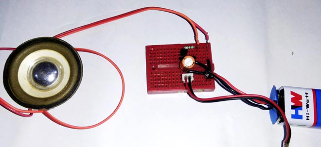
Amplifier is an electronic circuit or device which is used for amplification purpose and used mainly in sound reproduction as well in our electronic industry widely. There are many types of amplifier available by using different components like transistor based amplifier, op-amp based amplifier, transformer based amplifier. Sometimes we use a Preamp Circuit in circuits for pre-amplification of weak signal when the audio source sound level is too low. Pre-amlification of low level signals is necessary before feeding them into a power source, for clear and noiseless sound. In this project, we will build a Simple Preamplifier Circuit using NPN transistor BC547.
Here we have used this Preamplifier circuit for amplifying the AUX output of Mobile phone and amplifying the voice input given by the condensor mic or microphone. Same has been demonstrated in the Video given at the end. Both the circuits are given separately below. You can also check our previous amplifire circuts below:
- Headphone/Audio Amplifier Circuit on PCB using LM386
- LM386 Based Audio Amplifier Circuit
- Simple Audio Amplifier using 555 Timer IC
- Simple Arduino Audio Player and Amplifier with LM386
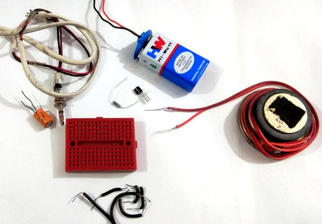
Components Required:
- Transistor BC547
- Bread Board
- 8ohm Speaker
- 100uF capacitor
- Power Supply
- Resistor 2.2k
- Aux wire or audio jack or MIC
- Connecting wire
- Jumper wire
Circuit Diagram and Explanation:
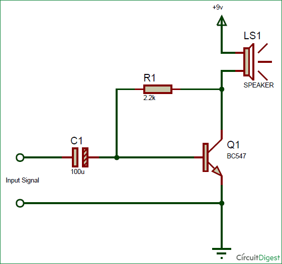
Below given is the Circuit diagram for Pre-amplification of AUX output of the Mobile Phone:
This is the simplest circuit for pre amplifier and we have used the same circuit for pre-amplification in our 555 based Amplifier.
Here the capacitor C1 is acting as coupling capacitor. Coupling capacitor is used as a filter to block out the DC component of the input signal, thus also called as DC blocking capacitor. It prevents the headphones or speaker to get damaged by the DC flowing of current.
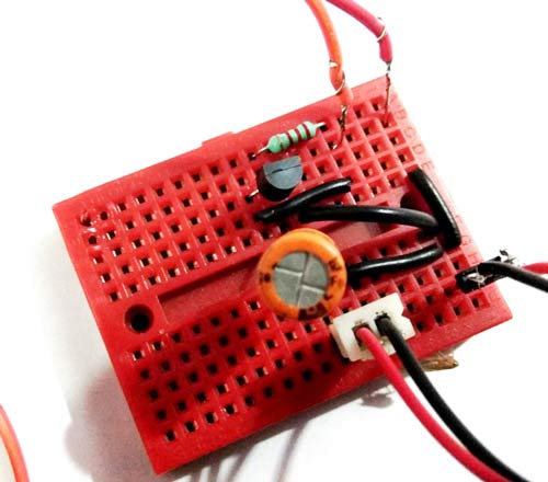
And as we know that Transistors can be used either as a switch or as a amplifier. So here this NPN Transistor BC547 is acting as Amplifier. In amplification setup, this transistor allows larger current to be flowed when we apply smaller voltage at its base. So here we are applying voltage at its base through the audio input signal by AUX jack and it allows larger current to be passed from the 9v battery source thought the speaker. In that way it is converting Electric energy into audio output.
Pre-amplification of audio input from MIC:
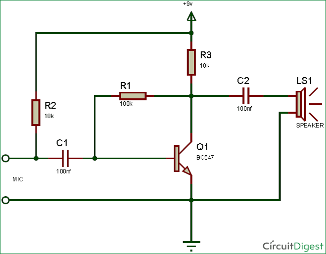
Here we have placed a MIC in place of playing music from the AUX jack. This circuit will amplify the voice input fed by the condenser mic, hence it is known as Microphone Preamplifier Circuit.



I have a wireless lapel mic but, its sound is very low and whenever I try to use it for recording, it gives negligible input to any of my recording devices. So, I was thinking if I could use the AUX preamplifier with the TS Pin (6.5mm) Mono lead that goes out from my wireless receiver (working on 233.5MHz frequency) because it sounds as a better option to me to build a preamplifier than buying a costlier lavalier microphone. But, I am confused which circuit should I use for the particular device I have i.e. the AUX one or the Mic one. As the mic preamplifier circuit is exclusive for the condenser mic only and not for other mics hence, I don't know which one I Should use. Please help me!