
In the previous tutorials, we demonstrated detailed design of 3.7V to 5V Boost Converter using MC34063 and 12V to 5V Buck Converter using MC34063. Today we will use the same MC34063 IC to build a DC to DC Boost Converter circuit which can convert small voltage like 3v to higher voltage upto 40v. So here MC34063 IC is used a Adjustable DC-DC Converter.
Components Required
- MC34063 buck/boost converter
- 0.22 Ohm resistor
- 180 Ohm resistor
- 2k2 Ohm resistor
- 50k Potentiometer
- 1N5819 Schottky diode
- 170uH Inductor
- 330uF Capacitor
- 100uF Capacitor
- 1500pf Capacitor
- Burgstips or screw terminal
- 9v battery
- Multimeter
- Perf board, Solder wire and iron
IC MC34063
MC34063 pinout diagram has been shown in the below image. On the left side the internal circuit of MC34063 is shown, and on the other side the pinout diagram is shown.
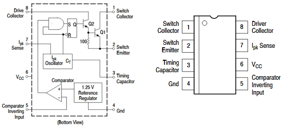
MC34063 is a 1.5A Step up or step down or inverting regulator, due to DC voltage conversion property, MC34063 is a DC-DC converter IC.
This IC provides following features in its 8 pin package-
- Temperature compensated reference
- Current limit circuit
- Controlled Duty cycle oscillator with an active high current driver output switch.
- Accept 3.0V to 40V DC.
- Can be operated at 100 KHz switching frequency with a 2% tolerance.
- Very low Standby current
- Adjustable output voltage
Also, despite these features, it is widely available and it is much cost efficient than other ICs available in such segment.
This chip can be used as buck converter (step down) and boost converter (step up) by changing the configuration of hardware and components.
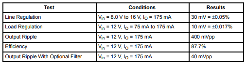
In step up configuration, it can deliver 175mA at 8-16 volt input voltage:
Circuit Diagram
Circuit diagram for Variable Output DC-DC Converter is given below:

Adjusting the Output Voltage of MC34063 based DC-DC Converter
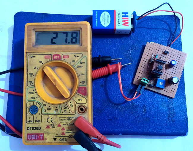
Here in this project we have used this chip to build a Variable Output Voltage DC-DC Converter as step up converter with voltage adjustable configuration. Here the 9v is applied as input voltage to the circuit which can be boosted to around 30 Volt by using potentiometer.
Formula to calculate output voltage given below:
Vout = 1.25(1+ (R2 / R1))
Here we have used R2 as 2.2k and R1 as 50k, so the output voltage will be:
Vout = 1.25 ( 1 + (50k/2.2k))
Vout = 29.65
Desired output voltage can be generated by changing the values of R1 and R2. So this is how this small circuit can be used variable output DC-DC converter.
Also check other variable power supply circuits: 0-24v 3A Variable Power Supply using LM338, and LM317 Variable Voltage Regulator Circuit.
Comments
I want to make this type of
I want to make this type of circuit with higher ampear rating any idea..
This device is limited to 1
This device is limited to 1.5A output.
Download the Datasheet for more info https://www.onsemi.com/pub/Collateral/MC34063A-D.PDF
Error in circuit diagram
Please note that the circuit diagram has R3 in the wrong position. R3 should beconnected beteen VCC and pin 7, pin 6 should be connected to VCC. I have blown two of these devices in above configuration as the current limiting will not function correctly.

if we give 12 v ,5 amp input to this circuit so what output ampear is we get???