Hi,
The ckt as as draw as attached, is a auto/manual control panel board for pump-motor and trying to configure to run with MCU control auto operation and manual (with start/stop button in board).
With the panel here i have included 2 nos relay: Relay-1, NO, parallel connected to START BUTTON and Relay-2, NC, series connected with STOP BUTTON for the purpose.
From the ckt, my perception is as follows:
1) Manual operation is found to be correctly.
2) For the case of auto operation: when relay-1 close, the loop of the COIL (CONTRACTOR) closed through Relay-2 and the COIL(CONTRACTOR) is energized, "R" is given to load-motor.
BUT the STARTING CAPACITOR not getting supply through Terminal-C2 of the START button in this arrangement of Auto mode. Then how "Y" will be provided to Motor..
Therefore my question is,
1) Is this connection is correct for the operation without that of starting capacitor arrangement??
2) If not How should I connect to provide phase to STARTING CAPACITOR to keep manual/auto both operation?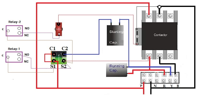
Thanks..

C1 and C2 > NO contact push button switch, and
S1 and S2> is another NO contact push button switch.
Red colourd as viz in above picture is one NC contact push button switch.
TNX.

Bradyen
PermalinkIs this a DOL starter? It is hard to help without knowing what C1, C2, S1 and S2 is doing!! Are they just a terminal block?
- Log in or register to post comments
Joined August 14, 2018 44Tuesday at 03:25 PM