
Security systems play an important role in our day to day lives and there we can find a lot of different types of security systems with different kinds of technologies and with different price range. Being an electronic enthusiastic you can make a simple security system by spending few bucks and some spare time. Here in this article I am sharing a DIY guide to make a simple Raspberry pi and PIR sensor based motion detector alarm which will turn on the buzzer when the PIR sensor detects any human movement in the area. We also covered a simple PIR sensor based motion detector circuit in one of our previous articles where we covered the working of PIR sensor in detail.
Components Required
- Raspberry Pi 3 (any model)
- PIR Sensor
- Buzzer
- Breadboard
- Connecting wires
Working of PIR sensor
Passive Infrared (PIR) sensor is called passive because it receives infrared, not emits. Basically it detects any change in heat, and whenever it detects any change, its output PIN becomes HIGH. They are also referred as Pyroelectric or IR motion sensors.
Here we should note that every object emits some amount of infrared when heated. Human also emits infrared because of body heat. PIR sensors can detect small amount of variation in infrared. Whenever an object passes through the sensor range, it produces infrared because of the friction between air and object, and get caught by PIR.
The main component of PIR sensor is Pyroelectric sensor shown in figure (rectangular crystal behind the plastic cap). Along with this, BISS0001 ("Micro Power PIR Motion Detector IC"), some resistors, capacitors and other components used to build PIR sensor. BISS0001 IC take the input from sensor and does processing to make the output pin HIGH or LOW accordingly.
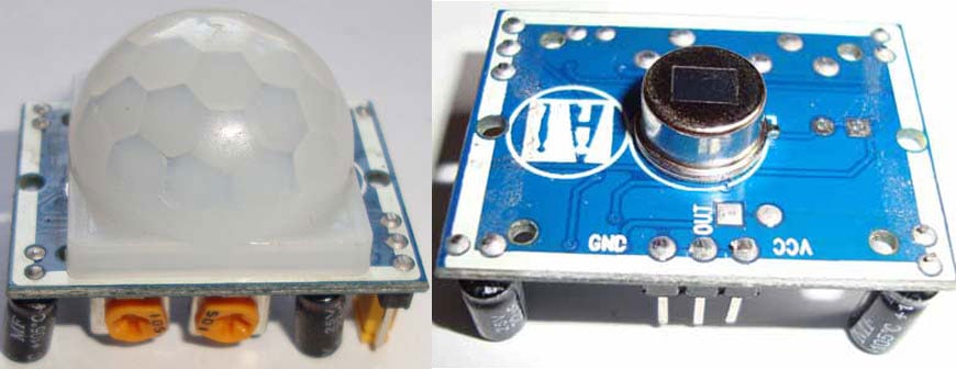
Pyroelectric sensor divide in two halves, when there is no motion, both halves remain in same state, means both senses the same level of infrared. As soon as somebody enters in first half, the infrared level of one half becomes greater than other, and this causes PIRs to react and makes the output pin high.
Pyroelectric sensor is covered by a plastic cap, which has array of many Fresnel Lens inside. These lenses are curved in such a manner so that sensor can cover a wide range.
Circuit Diagram for Raspberry Pi and PIR Sensor based Motion Detector

As shown in the above schematic diagram for Raspberry Pi and PIR sensor based motion detector, the positive pin of PIR sensor is connected with the pin 4 (5v) and ground pin of PIR sensor is connected with Pin 6 (Ground ) of Raspberry Pi (You can find here the Pin Diagram of Raspberry Pi). The output pin of PIR sensor is connected with the GPIO 23 of Raspberry pi which is used to give input to Raspberry Pi. The GPIO pin 24 which is declared here for output is connected with positive of buzzer, and ground of buzzer is connected with the ground (pin 6) of raspberry pi.
Python Code for Raspberry Pi:
The Python code for this raspberry pi and PIR sensor based motion detector is quite simple and could be understood easily with the comments inline in the code section below. I declared the GPIO pin 23 and 24 as input and output pins.
while True:
  if GPIO.input(23): #If there is a movement, PIR sensor gives input to GPIO23
     GPIO.output(24, True) #Output given to Buzzer through GPIO24
     time.sleep(1) #Buzzer turns on for 1 second
     GPIO.output(24, False)
A ‘while’ loop is used as ‘True’ so the contents inside the loop will always execute. if GPIO.input(23): statement detects if GPIO pin 23 is high, and if the same is true it makes the output PIN 24 high. The function time.sleep(secs) is used to pause the program in python for particular time where ‘secs’ is the time in seconds. So here we used to pause it for 1 second. In the next line we made the output on 24 as false so buzzer stops until the loop begins the next iteration, as While loop is set always true without any pre-condition.
Complete Project Code
#Raspberry Pi Motion Detector Code
import RPi.GPIO as GPIO
import time
GPIO.setmode(GPIO.BCM)
GPIO.setup(23, GPIO.IN)
GPIO.setup(24, GPIO.OUT)
while True:
  if GPIO.input(23): #If there is a movement, PIR sensor gives input to GPIO 23
     GPIO.output(24, True) #Output given to Buzzer through GPIO 24
     time.sleep(1) #Buzzer turns on for 1 second
     GPIO.output(24, False)
     time.sleep(5)
  time.sleep(0.1)
Comments
You just have to make the connection as shown in the circuit diagram, the picture of breadboard is only for reference. Just follow the circuit diagram and make the connections
i have tried many different approaches to this but no matter what i try it wont work out. i would be much obliged if you could run me up with reference material. you know it better than me im sure
AttributeError: module 'Rpi.GPIO' has no attribute 'Input'
What does that mean? Is there code that needs to go in before the first line?

hi. i wanna ask. how do you connect the jumpwire to the breadboard? based on above article, you just show the circuit of raspberry pi only. or the breadboard can be pin to any place ? i just wondering. i try to do this but the buzzer didnt give a beep sound. please help me