
 using USB Port")
The STM32 Development Board housing the STM32F103C8 Microcontroller is getting increasingly popular thanks to its ARM Cortex M3 architecture, it has high operational speed and more peripheral options. Also since, this board can be easily programmed using the Arduino IDE it has become a preferable choice for many hobbyists and engineers for quick prototyping.
In our previous tutorial we learnt the basics of the STM32 Development Board and also programmed it to blink an LED. But there was one huge drawback with it. In order to program the Board we utilised a FTDI programmer module and also had to toggle the boot 0 jumper between and 1 position while uploading and testing a code, which is surely a daunting task. Also the mini-USB port on the Development board was left totally unused. The reason for doing that is, when the STM32 development board is purchased it does not come with an Arduino ready boot loader and hence the board will not be discovered by your computer when connected through the USB.
Hopefully though, there exists an experimental boot loader developed by LeafLabs for Maple mini boards. This boot loader can be flashed into the STM32 once and thereafter we can directly use the USB port of the STM32 board to upload programs just like any other Arduino boards. However this boot loader is still in developmental stage at the time of documenting this tutorial and is not advisable for critical applications. Before proceedings with this tutorial make sure you have read the previous tutorial to understand the basics of this board including details about the specifications and pin-outs.
Materials Required
- STM32 – (BluePill) Development Board (STM32F103C8)
- FTDI Programmer
- Breadboard
- Connecting wires
- Laptop with Internet
Circuit Diagram
To program the STM32 Blue Pill board directly through USB port we need to first flash the Maple boot loader into the MCU. To do this we need to use a Serial FTDI board. This board is connected to the Rx and Tx pin of the STM32 as shown below.
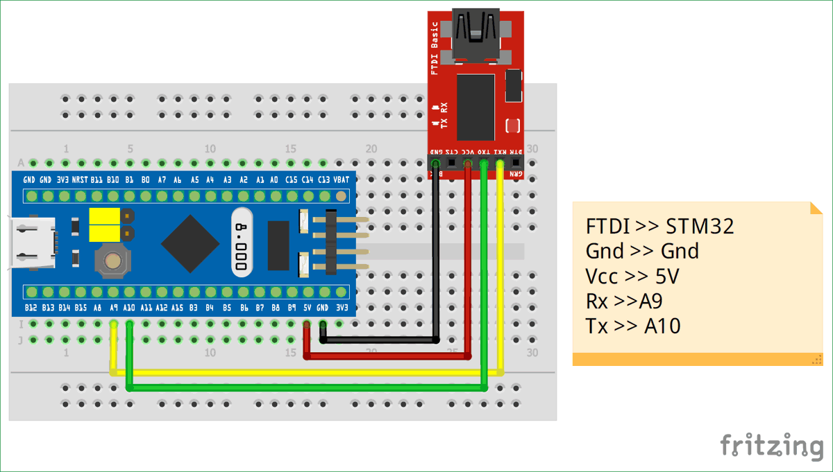
The Vcc pin of the FTDI board is connected to the STM32 5V pin of power the board. The ground is connected to the Ground of STM32. The Rx and Tx pin of the FTDI board is connected to the A9 and A10 pin of the STM32 respectively. Where the A9 is the Tx pin of STM32 MCU and the A10 is Rx pin.

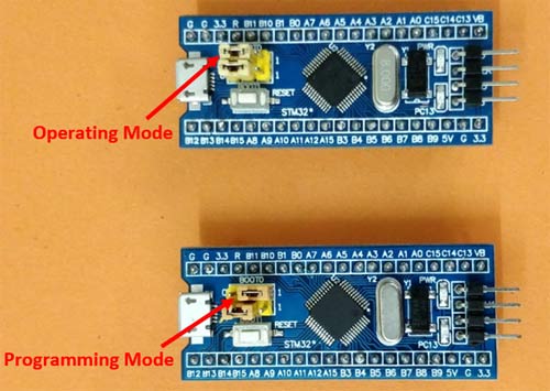
Make sure the boot 0 jumper pin on the board is set to 1 (programming mode) while uploading the boot loader. Once the boot loader is flashed this pin can be changed back to initial position (operating mode).
Uploading the Maple Boot loader to STM32 Development board
Once we have made the above connection connect the FTDI board to your computer and follow the steps to flash the boot loader into the STM32.
Step 1: We have to download the boot loader program file binaries (bin file) form the github page. There are many versions of bin file, for the Blue Pill board use this github link and click on the download button to download the bin file.
Step 2: Next we have to download and install the STM Flash loader software to flash the downloaded bin file into STM32. Click on this link to get into the ST website and scroll to the bottom and click on get software
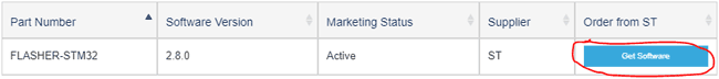
Step 3: To download the software you have to enter your E-mail address and the download link will be sent to your E-mail. Then follow the link back to the website and click on get software again and you download will begin. Yes it’s a bit frustrating but this is how it should be done. Don’t forget to check your spam folder for the E-mail, sometimes it takes a couple of minutes for the E-mail to arrive.
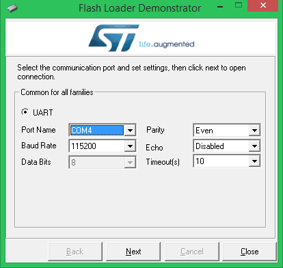
Step 4: Once downloaded install the software, make sure your STM32 board is connect to your computer though FTDI board and then launch the software. The software will automatically detect the COM port if not use the Device manager and make sure you select the correct COM port number. In my case it is COM4. Leave the rest of the setting as it is as shown below.
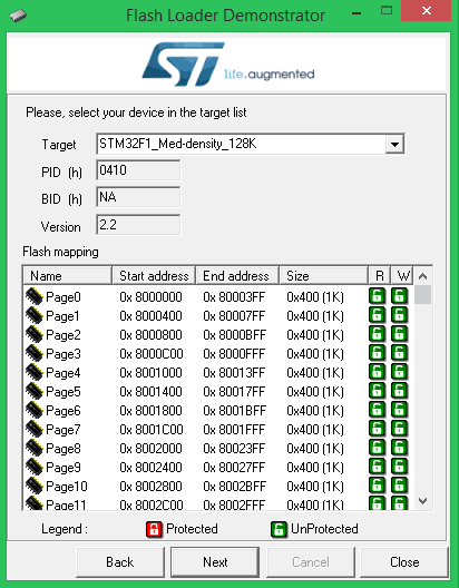
Step 5: Click on the Next button twice and the software will again automatically detect the board details and display as shown below. The board we are using is STM32F1 with 128K flash memory.
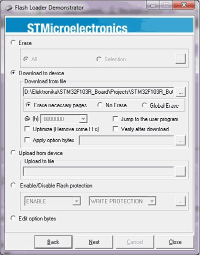
Step 6: In the next step, select Download to device and browse to the location where we downloaded our bin file in step 1 and select it. Click on next.
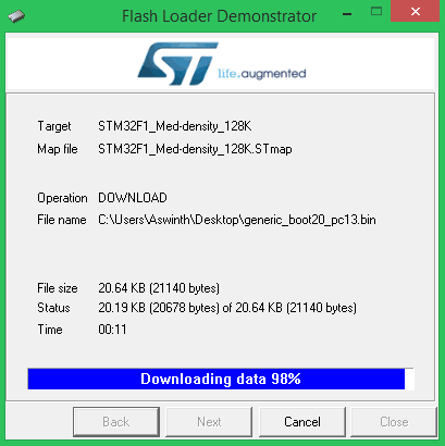
Step 7: The software will download some required files as shown below and will then begin the process of flashing.
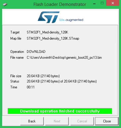
Step 8: Once the flashing is completes successfully, we will get the below screen. Click on close and exit the application. We have flashed the STM32 board with Arduino boot loader successfully. Now we have to prepare the Arduino IDE and install the drivers before we can program the STM32 board.
Preparing the Arduino IDE and Installing the Drivers
Follow the below steps to download and prepare the Arduino IDE to be used with the STM 32 Development board.
Step 1:- If you have not yet installed the Arduino IDE, download and install it from this link. Make sure you select your correct operating system.
Step 2:- After Installing the Arduino IDE open and download the required packages for the STM32 board. This can be done by selecting File -> Preferences.
Step 3:- Clicking on Preferences will open the below shown dialog box. In the additional Boards Manager URL text box paste the below link
http://dan.drown.org/stm32duino/package_STM32duino_index.json
and press OK.

Step 4:- Now go to Tool -> Boards -> Board Manager. This will open the Boards manager dialog box, search for “STM32F1” and install the package that appears.
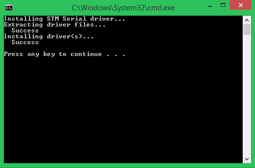
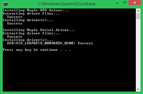
Step 5: After the package is installed, navigate to C:\Program Files (x86)\Arduino\hardware\Arduino_STM32-master\drivers\win where you will find install_drivers.bat and install_STM_COM_drivers.bat.
Step 6: Click on both the bat files and install the drivers. You will get a DOS screen as shown below.
Now the Arduino IDE is prepared for programming STM32 (Blue Pill) Development Board and the drivers are also installed.
Programming STM32 (Blue Pill) Directly Through USB Port
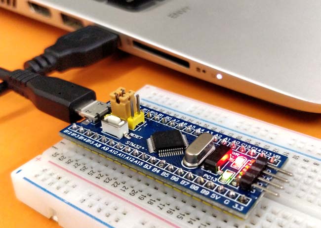
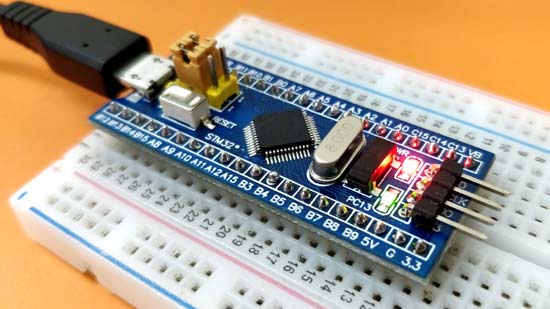
Remove the FTDI board and all the existing connections from you STM32. Just use the micro-USB port on the STM32 board to connect it to the computer as shown below. Make sure the jumper 0 pin is positioned back at 0 (Operating mode). Hereafter we need not toggle the jumper anymore to upload and run the programs.
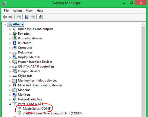
You computer should be able to discover the Board now. Wait for a while if you see any additional drivers getting installed. Then get into Device manager and check if your STM32 board is discovered under the COM and port section as shown below. Mine is connected to COM8 with the name Maple Mini.
Go to Tools and scroll down to find the Generic STM32F103C series as shown below. Then make sure the variant is 64k Flash type, CPU speed is 72MHz and change the upload method to STM32duino Bootloader. Also select the correct COM port according to the one on your device manager.
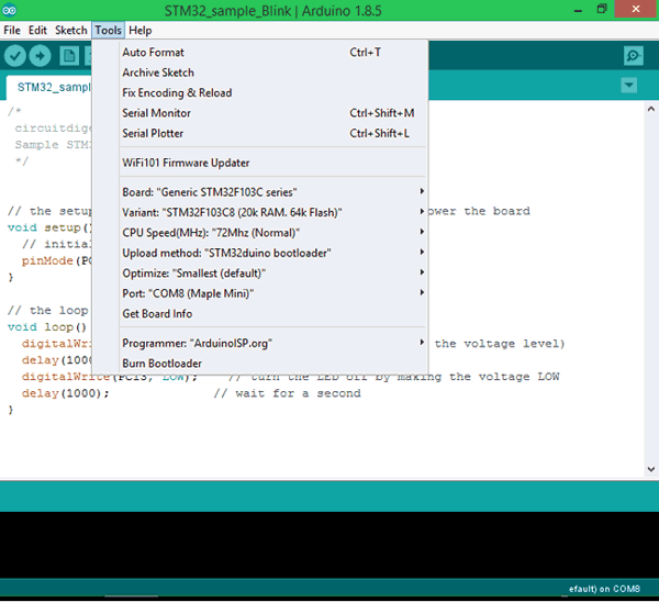
After all the changes are made, check the bottom right corner of the Arduino IDE and you should notice the following setting being set. My STM32 board is connected to COM8 but yours might differ

Now the Arduino IDE is ready to program the STM 32 Blue Pill Development Boards. Let us upload the Sample Blink Program from the Arduino IDE to the STM32 Blue Pill board to make sure everything is working properly. The example program can be found at
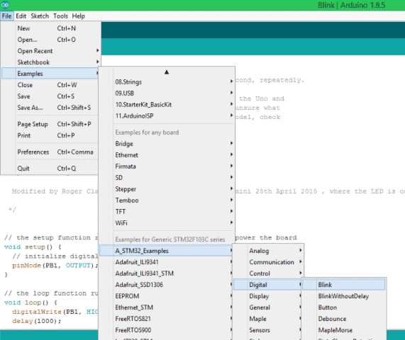
In the example program that opens, we have to make a small change. By default the program will be written for PB1 but on our board the on-board LED is connected to PC13 so replace all PB1 with PC13 and we are good to proceed. The complete example program which is modified can also be found at the bottom of this page.
The code inside the loop function alone is shown below, where we can notice that the PC13 pin is kept HIGH (on) for 1000 millisecond and then turned LOW (off) for another 1000 millisecond and this is done for infinite times since it is in loop function. Thus the LED appears to be blinking with an interval of 1000 millisecond.
digitalWrite(PC13, HIGH);   // turn the LED on (HIGH is the voltage level)
delay(1000);              // wait for a second
digitalWrite(PC13, LOW);    // turn the LED off by making the voltage low
delay(1000);              // wait for a second
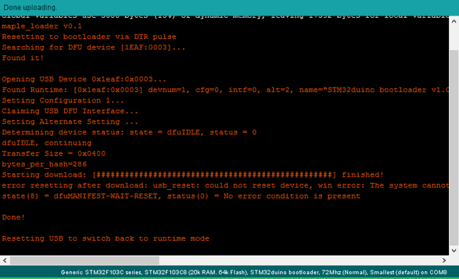
Press the upload button on the Arduino IDE and your program should get compiled and uploaded. If everything has worked as expected then you should see the following on your Arduino IDE console.
If the Program has been uploaded successfully then you should see the Green LED blinking at a 1 second interval as shown in the video below. You can also fiddle around with the program to increase or decrease the delay. Now you can start using the STM32 (Blue Pill) Development board like any other Arduino boards, that is you no longer need not change the position of jumpers or use external hardware to upload and test programs.
Hope you understood the tutorial and found it useful to get started with STM32 Board. If you have any problem leave them in the comment section, also tell me what projects we should try with this STM32 board in future.
Comments
Hi sir thank you for sharing now i can use the bluepills with STM32duino bootloader
Thanks in advance
Hi, I was wondering how can one re-roll back to old bootloader, is it the exact same procedure with different bootloader file?
the fritzing diagram and the pictures with the wiring are misleading. Only after I connected the VCC of the FTDI with 3.3 V of the stm32, the upload worked.
hello ! Is it possible to write a post about how make STM32 secure bootloader ? Thank you
hey, thanks for this tutorial!easy to understand, but there are a few things that i noticed (at least for me) that may need to be updated. First, is that there is no file that is related to the STM32 in the suggested location (C:\Program Files (x86)\Arduino\hardware\Arduino_STM32-master\drivers\win). I had to search for "maple drivers stm32" on google, and find the github page with them to aquire them. Yes, I did follow the part where we add the file in preferences and download the board definitions.
Second is, for me, i still have to switch BOOT 1 to "1", in order for the sketch to run. I also have still have to keep them both in the "0" position in order for it to upload the sketch. Is the later normal? I am of course, fully able to upload the sketches via usb, so THANK you for that!
cheers!
dps
Hi,
I tried every single video and tutorial, for weeks now, even bought a 2nd board, no result. getting "No response from the target, the boo loader can not be started" from STM flashLoader demo.
How to pass this stage?
in Ardino IDE, I'm getting the error "http:// stm32flash.googlecode.com/
Using parser : Raw Bianry
Any body solved this problem, Please Help!!!

Hi,
after installing the bootloader, no green led is blinking. Still I tried to do blink example but it gives me error:
exec: "/bin/arm-none-eabi-g++": file does not exist
Error compiling for board Generic STM32F103C series.
Maybe you have some ideas that could help me? I would appreciate. Thanks in advance :)