

According to the FBI, home burglary occurs for every 13 seconds and 3 out of 4 homes in US will be broken into within the next 20 years says a 2017 Home burglary statistics report. In the world that is advancing rapidly with technology where cars could drive on their own and drones could capture your food, burglary should not be of much concern but the above statistics just proves it wrong. What is the point of all the buzz words like IoT, AI, Machine learning etc if I simply can’t feel safe being at home?
By the time I write this article there are a lots of IoT security systems in the market, but neither of them were personalized to my taste nor fitted into my budget. Being the tinkerer, I chose to build one by myself and that’s when I stumbled upon the Bolt IoT Platform where they claim to help us build IoT projects 80% faster with their Bolt IoT platform.
So, in this project we will build our own security system which can detect if a door/window is opened. The alarm can be activated or de-activated through voice commands via Google assistant and when an intrusion is detected it will also send a mail to you and your relatives warning them about it. Cool thing is that entire thing runs on cloud so it can be controlled from anywhere in the world. Intriguing right! So let’s get started…..
Materials Required
- Bolt Development Board
- Breadboard
- Hall effect sensor (A3144)
- LED
- Capacitor (50V, 10uF)
- Resistor 10K
- Magnet
- Connecting wires
Working Concept
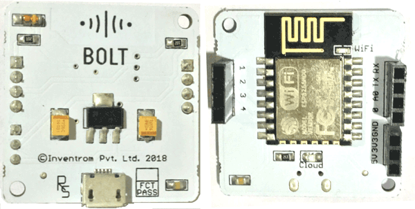
The Bolt development board is based out of the famous ESP8266 Wi-Fi module from Espressif semi-conductor. But here it has its own Bolt firmware running inside it, this helps us to access the GPIO pins (Digital Read/Write, Analog Read, PWM Write) etc through an API provided by bolt. Because of this fact the Bolt can be programmed with JavaScript, HTML or even Python. Since we have already many IoT projects with Raspberry Pi and Python I decided to stick on with python. To learn more about ESP8266 Wi-Fi module, follow the link and a simple IoT Security alarm can also be build using ESP8266. This project can be further extended to capture the image of Intruder using some microcontroller which supports camera interfacing. We have built this kind of Home Security System using Raspberry Pi.
The Bolt has 5 GPIO pins and 1 Analog pin all of which are connected to the cloud. So basically to write or read from these pins we have to use the API calls. In our hardware we will have a Hall Effect sensor and magnet mounted to the door. When the door is opened the magnet moves away from the hall sensor and the sensor will detect it and this can be read by the API calls and we can trigger a Buzzer. We will discuss more on this in the hardware section.
Circuit Diagram
The complete circuit diagram for this IoT based Door Alarm is given in the image below. The schematic was created using Fritzing

The connections are pretty much simple if you have doubts you can refer the table below. The complete set-up is powered by the Micro-USB cable which gets connected directly to the bolt development board.
Bolt Pin | Connected To | Pin Type |
Pin 0 | Hall sensor | Input |
Pin 1 | Buzzer | Output |
Pin 2 | LED | Output |
Pin 3 | Capacitor 1 | Input/output |
Pin 4 | Capacitor 2 | Input/output |
The Hall sensor acts as the input pin which will tell the board if the door is closed or opened. The LED connected to pin 2 is used to indicate status of the system. If it is active the LED will glow and if deactivated the LED will be turned off. The buzzer is activated when an intrusion has been detected. So far so good, but what is the purpose of Capacitor 1 and 2 and how is it used as Input and Output??? Well…For now you can think these capacitors as a memory storage element. But!! Why do we need one here?? I would like to tell you that now, but it would make a lot more sense if I explain this to you later in this article, so hang on to it.
Setting up the Bolt IoT Module
Before we proceed from here we have to set-up the Bolt hardware. It is very easy to do it, just install the bolt application on your phone and enter your Wi-Fi credentials so that your bolt could connect to your Wi-Fi and thus to the internet. Then you can visit the cloud page to get your Device ID and API key from there you are all good to go. You can visit the BoltIOT docs to know more about it. I also recommend toiling with it for sometime because there are other features like plotting a graph creating your own applications etc which we will not cover in this article.
Using the GPIO pins of the Bolt IoT hardware
As I said earlier, all the GPIO pins of the Bolt hardware are connected to the cloud and they can be controlled (read/write) only through the API. The API details can be found in the docs that I shared earlier. But let’s look into one as example. The API to read the status of the pin is explained in docs as shown below
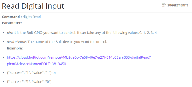
Here, what we are interested in this is API URL
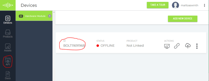
Here the API key is 44b2de6b-7e68-40e7-a27f-814b58afe008 and the device ID is BOLT13819450. But this is an example key and ID and will not be the same for your device. You have to visit cloud.boltiot.com to get the Device ID and API key of your device. The below snapshot can help you with that.
Once you get the API key and Device ID you simply have to replace the default values with your value and load the URL in your browser. You browser will respond back with the status of the pin with
{"success": "1", "value": "1"} or {"success": "1", "value": "0"}If the value is 1 then it’s a high and if 0 then it is a low. Similarly you can try the API links for all the commands like Digital Read, Write, Analog Write, PWM and even serial communication. Once you are done playing with it lets proceed with the actual program for this project.
Preparing the Python Environment
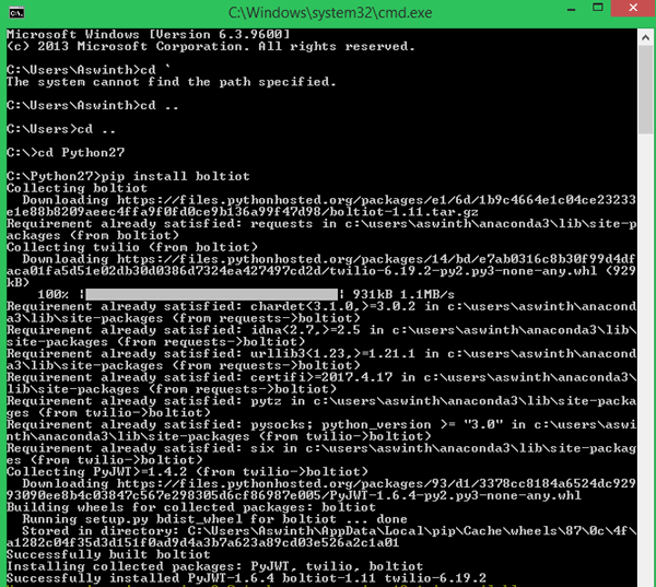
As I told earlier bolt can be programmed with JavaScript, HTML or Python. Here we will concentrate only on how to do it with python. We have to write the python script on our computer for which python should have been installed already. If you are new with all this I would advice reading this article to know how to install python and get started with it. Apart from that we also need to install two library packages in order for our program to work. You can add package to python using the pip install option, run the below commands on you terminal in python directory to install the packages. Open the windows terminal and navigate to the python directory mostly in the C://Python 27
Step 1:- Install pip if you have not installed before. Install it with below command
sudo easy_install pip
Step 2:- Inside the C://Python/Scripts directory install the requests package
pip install requests
Step 3:- The install the boltiot package using the below command
pip install boltiot
Once the installation is finished successfully your careen should look something like this below
That is it now we have open Python IDLE and start writing our actual program for our security system. But before that to activate or de-activate the alarm through Google assistant and to send E-mail we use the Google Assistant service and Web hooks service provided by IFTT. So let’s go ahead and set them now. If you are new with using IFTTT applets then it is recommended to read this article before proceeding.

Activating and De-activating the alarm using the Google Assistant
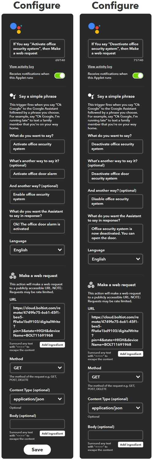
We have to create two applets (recipes) for this, one is to activate the alarm and the other is to de-activate the alarm. When the alarm is activated the capacitor connected to pin 3 should be charged and when the alarm is de-activated the capacitor connected to pin 4 should be charged.
The applet uses Google assistant for this service and web hooks get request for that service. The below screen shot shows how the applet is set for making the pin 3 high when Activating the alarm and making the Pin 4 High when deactivating the alarm through Google assistant.
What is with the use of capacitors?
The Capacitor 1 and 2 is used as memory elements. When the board receives command from the IFTTT the pin 3 and 4 will act as output pin. Based on the command the board will charge either the Capacitor 1 or the Capacitor 2.
Now when the IFTTT operation is completed the Python code makes the pin 3 and 4 as input pin, by reading the status of these pins the python code will understand if it should activate or deactivate the alarm based on which capacitor has charge. Simply put it is a small hack to interface the IFTTT with Python. It would have been a lot easier if Bolt platform has provided a virtual bit but said that is not an option here.
Sending E-mail when Intruder is detected
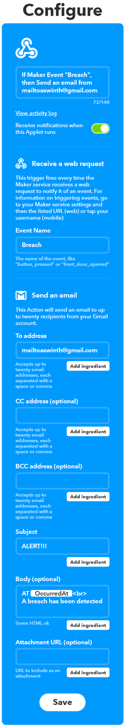
The third applet would be to send an E-mail when the intruder is detected. This can be done by using the web hooks and Gmail service on IFTTT. The Webhooks service will give us a URL which when loaded will trigger that pre-defined Email. The snapshot of the applet is shown below. You can customize the receiver ID and text as you wish. This URL will then be triggered in the python script using the requests library if an intruder is detected.
Python Program Explanation
The complete python code for this IoT Security Alarm can be found at the end of this project. In this section let’s break the code into small snippets and try to understand them. The overall aim of the python script is to check if the alarm is activated or de-activated and if activated we have to check if the door is opened and if opened we have to trigger an E-mail and turn on the buzzer.
We already know that the capacitor on pin 3 will be high if we have to activate the security system and the capacitor on pin 4 will be high if we have to de-activate the security system. So we simply have to read them in our python script to activate or de-activate the alarm.
We begin the program by importing the time, requests and boliot library. Out of which the time library is added in python by default, but you have to manually install the requests and boltiot packages as we discussed earlier else you will get an error on these lines.
import time #Import time to peform delay operations
import requests #use requests to send mail via webhooks IFTTT
from boltiot import Bolt #Import boliot to control GPIO pins through API
Next we enter the credentials of the device such as the API key and the Device ID. Only with these two values you can access any GPIO pin on the device. Do not share these with public if since they can be used by anyone to control your GPIO pins.
api_key = "4749fe75-6c61-45f1-bee5-f9a6a1bd9103" #Get your API key from Blot Cloud Website
device_id  = "BOLT11691968" #Get your Bolt device ID form Bolt Cloud Website
mybolt = Bolt(api_key, device_id)
As discussed on the API section we will get response when we perform a digital Read in the form of string, so I have assigned those string values to two variables so that we can use them in our program easily.
HIGH = '{"value": "1", "success": "1"}' #This will be returned by bolt API if digital read is high
LOW = '{"value": "0", "success": "1"}'#This will be returned by bolt API if digital read is low
Inside the infinite while loop, we have two other loops. One will be executed if the alarm is activated from the Google assistant and the other will be executed if the alarm is de-activated. By default the de-activated loop will be executed if no command is received.
Here, have to check if the alarm is activated by reading the pin 3 which is nothing but the capacitor. If the pin is high we make the orange LED to glow and then exit this loop and get into activated while loop. We check this for every 5 seconds just to make sure that we do not exceed the API rate limit provided by bolt, which is 30 calls per minute.
    while alarm == 0: #If alarm is off
        response = mybolt.digitalRead('3') #check if it is being activated
        if (response == HIGH):
            print("Security System is activated")
            mybolt.digitalWrite('2', 'HIGH') #Turn on LED to indicate Alarm is activated
            alarm = 1
        elif (response == LOW):
           print ("Waiting for Security System to be activated....")
        else:
           print ("Problem in getting value form pin 3")
       time.sleep(5) #check once in every 5 seconds to avoid exceeding API rate limit
Similarly, inside the activated while loop, we have to check for pin 4 to know if the alarm is being de-activated. If de-activated we turn off the orange loop and get back to the de-activated while loop. Else we have to check the magnet if it is present close to the hall sensor by reading the pin 0. If the pin is high then it means that magnet is away from the sensor indicating that the door has been opened. So we have trigger the buzzer and also trigger the mail using the requests package. Else we keep monitoring the sensor for every 5 seconds. The code to do the same is shown below
while alarm == 1: #If alarm is on
        response = mybolt.digitalRead('4') #check is it is being de-activated
        if (response == HIGH):
            print("Security System is De-activated")
            mybolt.digitalWrite('2', 'LOW')#Turn off LED to indicate Alarm is De-activated
            alarm = 0
            time.sleep(5)
        elif (response == LOW):
            print ("Security System is currently active can be deactivated from google assistant")
        else:
            print ("Problem in getting value form pin 4")
        response = mybolt.digitalRead('0') #check if hall sensor is triggered
        if (response == HIGH): #if magnet is not present
            print ("Alert! Security breach Buzzer ON")
            mybolt.digitalWrite('1', 'HIGH')
            requests.get('https://maker.ifttt.com/trigger/Breach/with/key/i6nPcZ5ZlzaVdbYITw6VGcpMkrVO5GqAX049cHEBDt') #webhook link to trigger mail through IFTTT
            time.sleep(5)
            mybolt.digitalWrite('1', 'LOW')
            print ("Buzzer OFF")
        elif (response == LOW):
            print ("No problem, all good!")
        else:
            print ("Problem in reading the value of button")
        time.sleep(5)
Time to test the Device
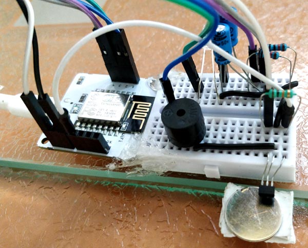
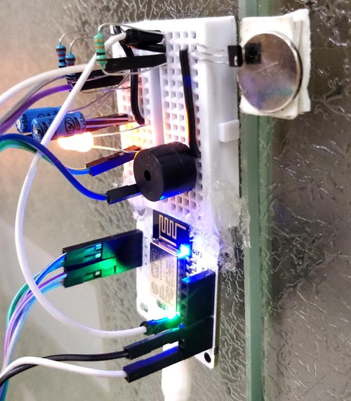
Once you are ready with the code we can start testing our project. Mount the board on the door’s frame and the magnet on the door itself. Make sure that the magnet stays close to the hall sensor. The idea is that the sensor should detect the magnet when door is closed and should not be able to detect the magnet when the door is opened. I used double side stick tape to mount my set-up and it looks something like this below.
Now run the python script on your computer and you should be able to see the status of the device from the print line statements in the python code. To activate the alarm simply say the command (Enabl Office Security System) to your Google assistant which have set in IFTTT, check the applet settings snapshots above. Once activated the orange light will start glowing indicating the status. Now, whenever the door is opened the alarm will go high with buzzer sound and also a mail will be sent to your Gmail inbox with the date and time of the breach. You can play around with the IFTT applets and the code to do more interesting stuff from here. But with this I am winding up this article.
The complete working video of this project can be found below. Hope you liked the project and would enjoy building something similar. If you have any quires you can use the forums to post them and I will try my best in answering it. Let meet in another interesting project until then Peace out..!
For more Security Alarm Project, just follow the link.
Complete Project Code
#PYTHON SCRIPT FOR IOT BASED SECURITY SYSTEM CONTROLLED THROUGH GOOGLE ASSISTANT - BOLT
#Program by B.Aswinth Raj
import time #Import time to peform delay operations
import requests #use requests to send mail via webhooks IFTTT
from boltiot import Bolt #Import boliot to control GPIO pins through API
api_key = "4749fe75-6c61-45f1-bee5-f9a6a1bd9103" #Get your API key from Blot Cloud Website
device_id  = "BOLT11691968" #Get your Bolt device ID form Bolt Cloud Website
mybolt = Bolt(api_key, device_id)
HIGH = '{"value": "1", "success": "1"}' #This will be returned by bolt API if digital read is high
LOW = '{"value": "0", "success": "1"}'#This will be returned by bolt API if digital read is low
alarm = 0 #Alarm is turned off by default
while True: #Infinite loop
    while alarm == 0: #If alarm is off
        response = mybolt.digitalRead('3') #check if it is being activated
        if (response == HIGH):
            print("Security System is activated")
            mybolt.digitalWrite('2', 'HIGH') #Turn on LED to indicate Aalarm is activated
            alarm = 1
        elif (response == LOW):
            print ("Waiting for Security System to be activated....")
        else:
            print ("Probelm in getting value form pin 3")
        time.sleep(5) #check once in every 5 seconds to avoid exceeding API rate lmit

    while alarm == 1: #If alarm is on
        response = mybolt.digitalRead('4') #check is it is being de-activated
        if (response == HIGH):
            print("Security System is De-activated")
            mybolt.digitalWrite('2', 'LOW')#Turn off LED to indicate Aalarm is De-activated
            alarm = 0
            time.sleep(5)
        elif (response == LOW):
            print ("Security System is currently active can be deactivated from google assistant")
        else:
            print ("Probelm in getting value form pin 4")
        response = mybolt.digitalRead('0') #check if hall sensor is triggered
        if (response == HIGH): #if magnet is not present
            print ("Alert! Security breach Buzzer ON")
            mybolt.digitalWrite('1', 'HIGH')
            requests.get('https://maker.ifttt.com/trigger/Breach/with/key/i6nPcZ5ZlzaVdbYITw6VGcp…') #webhook link to trigger mail through IFTTT
            time.sleep(5)
            mybolt.digitalWrite('1', 'LOW')
            print ("Buzzer OFF")
        elif (response == LOW):
            print ("No probelm, all good!")
        else:
            print ("Problem in reading the value of button")
        time.sleep(5)
Comments
There is nothing like uploading the code unlike Arduino.
Your simply have to type in the code in the online IDE and it gets uploaded in your board automatically like Over the air updates
Hi,
Great Project...
I want to implement something similar in one of my college projects. In the photo of the Bolt WIFi module below the circuit diagram photo, you have connected pins 3 and 4 somewhere on the breadboard. In the code you are reading pins 3 and 4. What are the input to those pins?

what is the procedure to upload the code to the bolt iot system?