Hi,
I have just finished building a crude charger for my 12V 9Ah Lead Acid battery using LM317. Everything works perfectly but I need to have a reverse polarity protection circuit for my charger since it will be handled by novice people.
Please suggest me a circuit which is simple and effective.I looked at few circuits but I am confused to use them since my load is a battery
Thanks

Hi Violet, thanks for the quick reply.
But I have already looked at the option of using a schottky diode. These diodes have roughly 0.4V drop across them and my charger has a charging current of 1.5A which is
P = 0.4 * 1.5 = 0.6W of loss in form of heat
So I am looking for an alternative.

Hi Bradyen welcome to circuit digest forums..
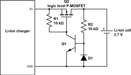
The most common reverse polarity circuit that is used for chargers is the one with P-Channel MOSFET. The circuit diagram is given below

This is by far the best circuit I have come across. The MOSFET conducts only when the battery is connected with proper polarity, during reverse polarity the MOSFET remains turned off and thus protects the charger and load.
This circuit also does not have a fuse hence there will be no damage of components and need for replacements or repairs. And select a MSOFET that has a very low drain to source resistance (RDS) and you will get a very less voltage drop across it. It will defiantly be efficient than using a Schottky diode
Hope it helps

Thanks Aswinth, on the first look I could not understand how th circuit works. But will google for more info and try it out on my test board. If everything works I am going to use it for my charger.
Thanks Again!

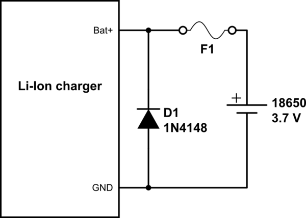
Using a MOSFET is a good idea, but is would just like to share one more option that uses a commonly available diode and fuse. Simple connect the diode in parallel to the charger output so that the conducts only if the battery is connected in reverse polarity also add a fuse in series to it.
So when then battery is connect wrong the diode will conduct safeguarding the charger and a high current will pass through it, since there is a fuse in series with it the high current will blow the fuse and open all connections. The circuit is shown below

As I told this circuit is very simple, but has its own downsides. One is that you have to replace the fuse every time there is a reverse polarity and the other is during reverse polarity the battery terminals are shorted periodically till the fuse is blown. This short is okay for Lead acid batteries, but should be avoided for lithium batteries


Violet
PermalinkI always use a schottky diode in series with the load, like shown below
This way the load will get supply only if the diode is forward biased, if it is reverse biased the diode will block the flow of current and thus protecting your circuit.
I commonly use the 1N5822 these diodes have less forward voltage drop and hence ideal for reverse polarity protection
- Log in or register to post comments
Joined August 16, 2018 42Thursday at 11:31 AM