

Batteries are most convenient power source to supply voltage to an electronic circuit. There are many other ways, to power up electronic devices, like adapter, solar cell etc but the most common DC power supply is Battery. Generally all the devices come with Reverse Polarity Protection Circuit but if you have any battery operated device which don’t have reverse polarity protection then you always have to be careful while changing the battery otherwise it can blow up the device.
So, in this situation Reverse Polarity Protection Circuit would be a useful addition to the circuit. There are some simple methods to protect the circuit from reverse polarity connection such as using a diode or Diode Bridge or by using P-Channel MOSFET as a switch on HIGH side.
Reverse Polarity Protection using Diode
Using a Diode is the easiest and cheapest method for Reverse Polarity Protection but it has a problem of power leakage. When the input supply voltage is high a small voltage drop may no matter, especially when the current is low. But in case of low voltage operating system, even a small amount of voltage drop is unacceptable.
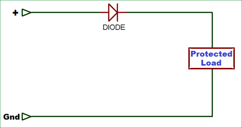
As we know the voltage drop across a general purpose diode is 0.7V so we can limit this voltage drop by using Schottky diode because its voltage drop is around 0.3V to 0.4V and it can also withstand with high current loads. Be aware while choosing a Schottky diode, because lots of Schottky diodes comes with high reverse current leakage so make sure that you will choose one with low reverse current (less than 100uA).
At 4 Amps, power loss by a Schottky diode in the circuit will be:
4 x 0.4W = 1.6W
And in ordinary diode:
4 x 0.7 = 2.8W.
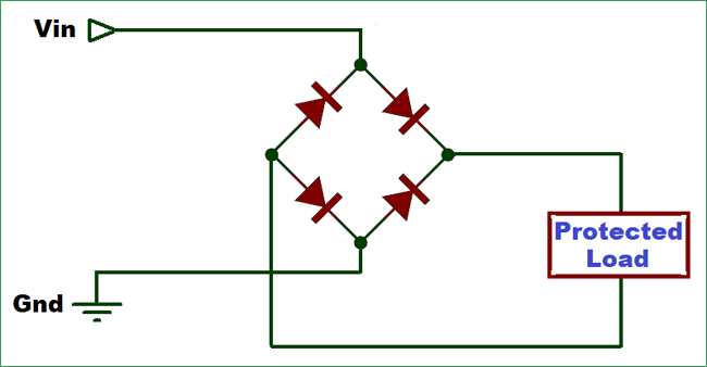
You can even use a Full-bridge rectifier for reverse polarity protection, as it is regardless of polarity. But bridge rectifier consists of four diodes, hence the amount of power waste will be twice of the power waste in the above circuit with single diode.
Reverse Polarity Protection using P-Channel MOSFET
Using a P-Channel MOSFET for Reverse Polarity Protection is more reliable than other methods, because of low voltage drop and high current capability. The circuit consists of a P-Channel MOSFET, Zener diode and a pull-down resistor. If the supply voltage is less than the Gate-to-Source voltage (Vgs) of P-channel MOSFET then you only need the MOSFET without diode or resistor. You just have to connect the gate terminal of the MOSFET to the ground.
Now, if the supply voltage is more than the Vgs then you have to drop the voltage between the gate terminal and source. Components required for making the circuit hardware is mentioned below.
Material Required
- FQP47P06 P-Channel MOSFET
- Resistor (100k)
- 9.1V Zener Diode
- Breadboard
- Connecting Wires
Circuit Diagram

Working of Reverse Polarity Protection Circuit Using P-Channel MOSFET
Now, when you connect the battery as per the circuit diagram, with correct polarity, it causes the transistor to turn ON and allows the current to flow through it. If the battery is connected backwards or in reverse polarity then the transistor turns OFF and your circuit gets protected.
This protection circuit is more efficient than others. Let’s analyze the circuit when the battery is connected in right way, the P-Channel MOSFET will turn ON because the voltage between gate and source is negative. Formula for finding the voltage between gate and source is:
Vgs = (Vg - Vs)
When the battery is connected incorrectly, the voltage at gate terminal will be positive and we know that P-Channel MOSFET only turns on when the voltage at gate terminal is negative (minimum -2.0V for this MOSFET or less). So whenever battery is connected in reverse direction the circuit will be protected by the MOSFET.
Now, let’s talk about the power loss in the circuit, when the transistor is ON the resistance between drain and source is almost negligible but to be more accurate you can go through the datasheet of the P-Channel MOSFET. For FQP47P06 P-channel MOSFET the Static Drain-Source On-Resistance (RDS(ON)) is 0.026Ω(max.). So, we can calculate the power loss in circuit like below:
Power Loss = I2R
Let’s assume the current flow through the transistor is 1A. So the power loss will be
Power Loss = I2R = (1A)2*0.026Ω = 0.026W
Hence, the power loss is about 27 times lesser than the circuit using single diode. That’s why using a P-Channel MOSFET for Reverse Polarity Protection is far better than other methods. It is little bit costlier than diode but it makes the protection circuit much safer and efficient.
We have also used a Zener Diode and a resistor in the circuit for the protection against exceeding gate to source voltage. By adding the resistor and the Zener diode of 9.1V, we can clamp the gate-source voltage to a maximum of negative 9.1V, hence the transistor remains safe.

I think the. Circuit has error. Zener should be between gate and battery positive.