
With the boom of Smart Phones, Internet of things (IoT), Industrial Automations, Smart Home Automation systems etc. the demand for internet is also growing exponentially. The technology has evolved so much that everything from our car to our refrigerator needs a connection to the internet. This raises other questions like; Will there be enough bandwidth for all these devices? Will these data be secure? Will the existing system be fast enough for all these data? Will there be too much conjunction on network traffic?
All these questions will be tackled by this upcoming technology called Li-Fi. So what is LiFi? The term Li-Fi stands for “Light Fidelity”. This is believed to be the next generation of internet, where Light will be used as a medium to transport data. Yes you read it right; it is the same Light that you use in your homes and offices which, with some modifications can be used to transmit data to all your devices that requires internet. In this project we will build a simple circuit to transfer Audio Data using Li-Fi. But first we will learn about Li-Fi Technology.
How Li-Fi Works
As told earlier Li-Fi uses light to transmit data unlike Radio waves. This idea was first coined by Prof. Harald Haas in one of his TED talk in 2011. The definition for Li-Fi can be given as “LiFi is high speed bi-directional networked and mobile communication of data using light. LiFi comprises of multiple light bulbs that form a wireless network, offering a substantially similar user experience to Wi-Fi except using the light spectrum”
Every LED lamp should be powered through an LED driver, this LED driver will get information from the Internet server and the data will be encoded in the driver. Based on this encoded data the LED lamp will flicker at a very high speed that cannot be noticed by the human eyes. But the Photo Detector on the other end will be able to read all the flickering and this data will be decoded after Amplification and Processing. The data transmission here will be very fast than RF. Here we are using Solar panel at the receiving end to sense light.
Transmitting data through photo diodes has been happening for a long time through our IR Remotes. Every time we pressed a button on our Television remote the IR LED in the Remote pulses very fast this will be received by the Television and then decoded for the information. But, this old method is very slow and cannot be used to transmit any worthy data. Hence with LiFi this method is made sophisticated by using more than one LED and passing more than one data stream at a given time. This way more information can be passed and hence a faster data communication is possible.
Now, we will see how we can transfer and receive audio signals using a simple LED and solar cell plate. If you are interested in this technology you can learn more about Li-Fi here.
Materials required:
- 5-6V Solar Panel
- 1 W LED or NeoPixel LED strip
- Aux cable
- 3.5 mm Jack
- 9V Battery
- Pre amplified speaker
We have two circuits one for Receiver side and other for transmitter side.
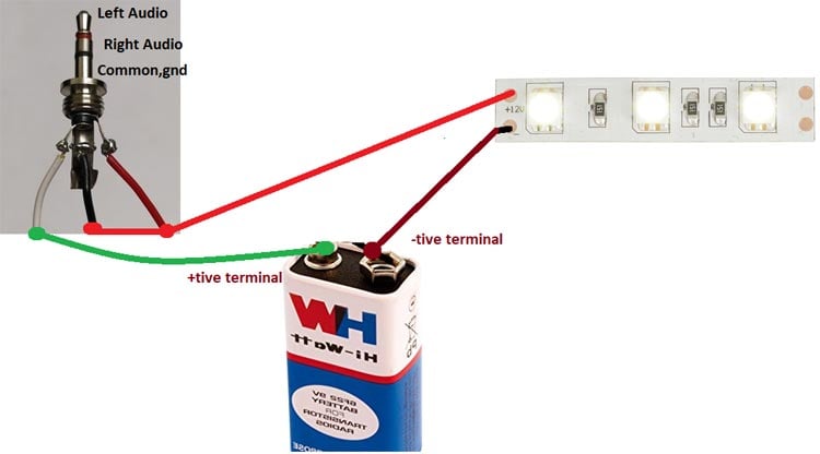
Transmitter Circuit for Li-Fi:
On transmitter side, we have white Bright LED and a battery which are connected to 3.5mm jack and jack will be connected to audio source. Here we are using battery to power up the LEDs because there is less power coming from the audio source which is not enough to power the LEDs. Connections are shown below in the circuit diagram:
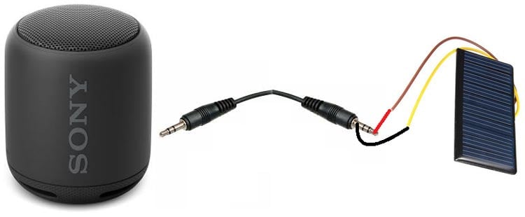
Receiver Circuit for Li-Fi:
On receiver side, we are using Solar panel and a speaker which is connected by an Aux cable. You can also make you own amplifier circuit for receiving end, which has been explained later in this article.
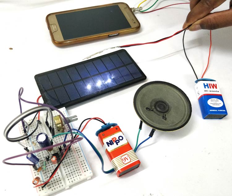
Working of Audio Transfer circuit using Li-Fi:
In transmitter side, when we connect 3.5mm jack to audio source LED will glow but there is no fluctuation in the intensity of light when the audio source is OFF. As soon as you play the audio, you will see that there is frequent change in intensity of light. When you increase the volume, LED’s intensity is changing faster than the human eye can follow.
Solar panel is so sensitive that it can catch small intensity change and correspondingly there is change in the voltages at output of solar panel. So, when the light of LED falls on the panel, voltages will varies according to the intensity of light .Then voltages of solar panel is fed into amplifier (Speaker) which amplifies the signal and giving the audio output through the speaker connected to the amplifier.
Output will come as long as solar panel is in contact of LED’s. You can put the LED’s at max. 15-20cm distance from the solar panel to get the clear audio output. You can further increase the range by increasing the area of solar panel and higher wattage Power LED.
You can make your own amplifier circuit to improve the voice quality like shown below.

Make your own Amplifier to Receive Li-Fi Audio:
Instead of using readily available speaker set, like we have used above, you can also make your own amplifier to reduce the noise. Here is one LM386 based audio amplifier circuit to receive he li-fi Audio.

- 100μF capacitor between the positive and negative power rails is used to decouple the power supply.
- Place a 0.1μF capacitor between pins 4 and 6, for more accurate decoupling of the power supply to the IC.
- A 10K Ohm resistor and a 10μF capacitor is connected in series between pin 7 and ground to decouple the audio input signal.
If audio is not clear through the speaker, rotate the knob of pot till the sound is not clear. Learn more about LM386 based Audio Amplifier here.
Note that the components values we are used are not critical. If you don’t have the components with the values given in the diagram, try with something close and it should work and make the connections close to the IC, use short wires for the connections because it causes extra noise.
Comments
Audio signal *IS* an electrical signal. Second, it is amplifying analog signal and not 'ones and zeroes' (which are also usually denoted as different voltage levels but not in this project), this project is *NOT* digital in essence, it is analog. It is obvious that you need to read *a lot more* and to clarify for yourself many things, I hope you complete your mini project and learn new things and clarify the things that are not clear to you now. Don't give up, read, read ... make, make ... repeat ;)
Audio signals a are analog. Have patience and read before you post your comments. Remember google is your best frnd.
Is it safe to connect battery to headphone jack of phone or will it cause any damages to phone please clarify my doubt
No it won't cause any damage to your phone unless you short circuited the left audio pin with right audio.
Sir, What can we do to increase the distance of transmission ?
Can we replace solar cells with photo-diode? In case if we do, will there be any changes in the circuit ?
Hoping for your response.
Misleading title. nothing new here , a friend did this in 1980 as a school project , used a bicycle lamp as the source and a photocell as receiver. quality is not good or range . you are just using the straight analog audio signal to amplitide modulate (AM as in medium wave radio) the light intensity. nothing digital at all. quality and range can be improved by using Frequency moduclation (FM as in vhf radio) of the signal , Totally different from the "LIFI" it is pretending to be. that uses true digital communication a totally different concept.

firstly, the signal from the 3.5mm jack is audio signal or electrical signal, secondly if electrical how can you use the Lm386 which is a audio amplifier to amplify a stream of one's and zero's which is output of the solar panel. please clarify my doubts as possible as possible because i choosed this project as my mini project.