

The MSP-EXP430G2 is a Development Tool a.k.a LaunchPad provided by the Texas Instruments to learn and practice on how to use their Microcontrollers. This board falls under the MSP430 Value Line category where we can program all the MSP430 series Microcontrollers. This beautiful shiny Red board is fascinating to learn just because of the very fact that it belongs to TI (Texas Instruments). Learning how to use TI Microcontrollers would defiantly be a mighty tool up in our sleeve because TI is really huge and has a wide verity of MCU’s to choose from for a very less competitive price.
In this series of tutorials, we will learn about this MSP430G2 LaunchPad and how to program it. Using this LaunchPad we can work with MSP430 Microcontrollers which offers 16-bit performance with an operational speed up to 16MHz. The tutorials are written for very beginners in electronics and hence every topic would be briefed as crisp as possible. The hardware required for these tutorials would be a normal computer and the MSP430 Value Line LaunchPad Development Toolkit with few other basic electronics components that you can easily find in your local electronics hardware shop. So without any further ado let’s dive into the Development Tool and check out what’s included in the box and how to use them. We will be able to Blink an LED at the end of this tutorial.
MSP430G2 LaunchPad Contents:
When you purchase the MSP430G2 LaunchPad Development Tool from TI or any other local vendor you will get the following materials included in your Box. The complete contents are also shown in the picture below. Also note that this is applicable as on 2018 the earlier and future versions might have different Contents
- MSP-EXP430G2 Development Board
- MSP430G2452 and MSP430G2553 Microcontrollers
- Mini USB cable
- Micro Crystal Oscillator (32.7kHz)
- Quick Start Guide

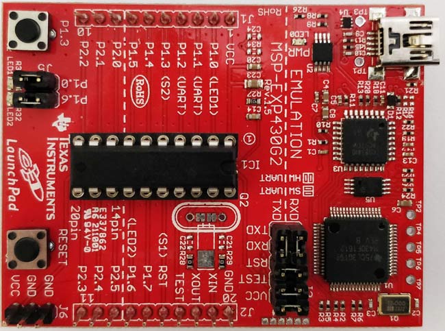
MSP-EXP430G2 Development Board:
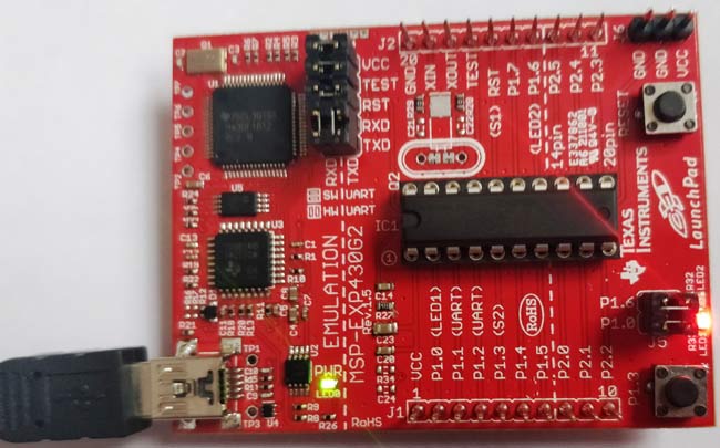
The gorgeous red colour board is the MSP-EXP430G2 Development Board. This board can program TI Microcontrollers that fall under the MSP430 series. The main purpose of this board it to upload code from the computer to the MCU and read serial data from the MCU for debugging purpose. It also provides the pin-out for each pin of the MCU and also two LEDs and a push button to make development easy. The board has evolved a lot since its launch and the one shown below is the MSP_EXP430G2 Rev1.5. To know about the function of each jumper and button on the board watch the video at the end of this page.
MSP430G2452 and MSP430G2553 Microcontrollers:
As told earlier the MSP430 Development Board can be used to program Microcontrollers that fall under the MSP430 Value line series. But, with this development kit, TI provides us two Microcontrollers from the MSP430 series which are the MSP430G2452 and the MSP430G2553. Both are 20 Pin DIP IC’s with decent performance. By default, the MSP430G2553 will be fixed to the IC socket of your Development board and the MSP430G2452 will be provided separately. The technical specification of both the MCUs are tabulated below
| MCU Name: | Technical Specification |
| MSP430G2553 | 16kB Flash, 512B RAM, 16GPIO, 2×16-bit Timer, Watch Dog Timer, Brown Out Reset, 1×USI(IIC/SPI/UART), 8ch 10-bit ADC, 8ch Comparator, Capacitive Touch IO Module |
| MSP430G2452 | 8kB Flash, 256B RAM, 16GPIO, 1×16-bit Timer, Watch Dog Timer, Brown Out Reset, 1×USI(IIC/SPI), 8ch 10-bit ADC, 8ch Comparator, Capacitive Touch IO Module |
As you can see the MSP430G2553 has better specifications than the other, it also has a UART module which would be very handy while debugging using Energia. Hence in this series of tutorials, we will be using the MSP430G2553 to explore all the functionalities of this Development kit.
Mini USB cable:
The mini USB cable is used to connect the board the Computer when a program has uploaded the data (in form of hex code) will flow from the computer to the board through this cable. Also during debugging (Serial Monitor), the data from the MCU will be received via this cable.
This cable also provides power to the board, so you can even use a mobile charger to power your board through this cable after uploading the program.
Micro Crystal Oscillator:
TI Also provides a 32kHz micro crystal Oscillator along with the Development Kit. This Crystal can be soldered to the Board but it is completely optional. Because the MSP430G2553 IC has an internal Oscillator of 16MHz which should be sufficient for us to get started.
Powering and Testing your Development Board:
Before we start anything TI would have already uploaded a sample Program on your MSP430G2553 Microcontroller, so let us power the board and check if it is working. You can power board through the mini USB jack and once you do it, you should notice the LEDs (red and green) at the bottom left corner of your board glowing alternatively. You can then press the push button connected to P1.3 to check if the internal temperature sensor is working. Yes, the MSP2553 has an internal temperature sensor, after pressing the button just rub your fingers to warm it up and place it on the IC you can notice the Red LED turns on to indicate the rise in temperature. Cool!! Right?? Okay now, let us move on to the Software Environment.
Programming Software (IDE) for MSP430 LaunchPad:
Texas Instruments allows us to program their Microcontrollers through a variety of Environments. The Official one is the Code Composer Studio commonly known as the CCS. This software is also free but using it is requires some minimal level of experience with Microcontrollers.
Since this series of tutorials are targeted for absolute beginners we use another Development Environment called Energia. Energia is an Open source and free Environment that enables us to program the TI Microcontrollers easily. The main aim of Energia is to make programming TI MCU’s as easy as programming in Arduino. So Energia is an Equivalent for Arduino that supports Texas Instruments Microcontrollers. People who have used Arduino will agree more on this once they download and launch the Energia IDE.
Downloading and launching the Energia IDE:
As said earlier the Energia is an open source and free Development environment, and it can be downloaded from this Download link. Select the Version based on your operating system, for windows you should notice a ZIP file being downloaded. After downloading the ZIP just extract it on your preferred location and open the folder. You find the application named Energia. Launch it and it should Look something like below.
Arduino users don’t be surprised as it just might look like your Arduino IDE has dressed up like a Santa to appear as Energia. The resemblance of both Arduino and Energia are same because they both are built on top of a platform called Processing.
Blinking an LED on MSP430G2:
Now, that we are ready with our hardware and software let us try a basic example program from Energia to blink the on board LED. Before we start programming we have to know the pin names of each pin on our MSPG2553 IC. Because we will be using these names while programming our board. The following picture from the Energia website will help us understand the name and functionality of each pin. Based on the Revision of your board the image might vary slightly.

Save this image, as we will need it all time while programming our MSP430 through Energia.
Understanding the Example Blink Program:
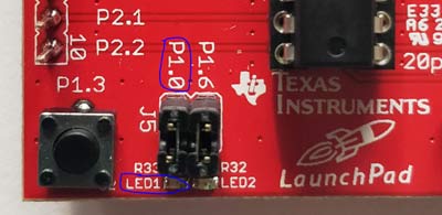
Let’s, start with the Example blink program which will blink the LED1 (red colour) which is connected to the P1.0 pin of your Microcontroller. The LED and its marking on my board is in the below picture.
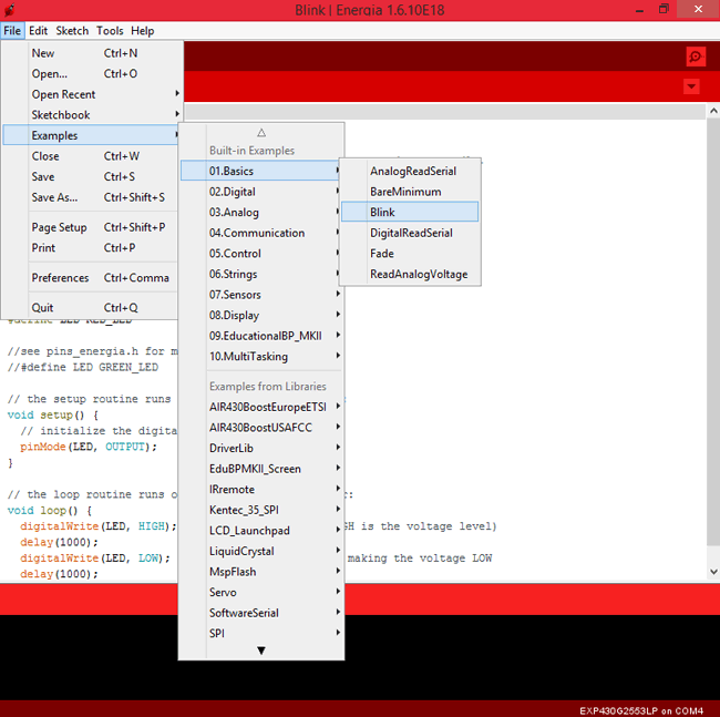
To open this example program navigate to File->Example->Basics-> Blink as shown below
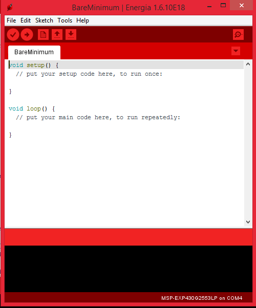
The following program will appear on your IDE
#define LED RED_LED
// the setup routine runs once when you press reset:
void setup() {
  pinMode(LED, OUTPUT);     // initialize the digital pin as an output.
}
// the loop routine runs over and over again forever:
void loop() {
  digitalWrite(LED, HIGH);   // turn the LED on (HIGH is the voltage level)
  delay(1000);               // wait for a second
  digitalWrite(LED, LOW);    // turn the LED off by making the voltage LOW
  delay(1000);               // wait for a second
}
Lets break the above code into line by line and see what it actually means, but before that let us understand the basic programming structure of Energia. Every Energia Program will have two mandatory functions, they are void Setup() and void Loop().
The code present inside the void Setup() will be executed only once and the program present inside the void Loop() will be executed for ever. All the pin declarations and initialisations will be done inside the Setup() and the main program which has to be executed forever will be written inside the void Loop(). You can think of void Loop() as an equivalent to while(1) (Infinite while loop). With this in mind let us start exploring above code line by line.
The first line of the program is called macros. The Energia IDE is smart enough to understand words like RED_LED, GREEN_LED, TEMP_SENSOR and much more. These are nothing but the name of the pins to which the hardware is connected to. This is possible because the Red and Green Led’s are hardwired on our board and hence the MCU pin to which it’s connected to is known. Again for the comfort of programming we use a Macros which says that instead of using the name “RED_LED” in my program I will use only “LED” by using the #define as shown in the below line.
#define LED RED_LED
Next we come into our void setup() function, this is the place where we tell our MCU which pins should be used as input pins and which should be use as output pins. In our program we only use a LED and it is a Output device, so we declare it to be an output pin like shown below
void setup() {
  pinMode(LED, OUTPUT);     // initialize the digital pin as an output.
}
The line pinMode() is used to say that I am going to declare input/output pins and then we say the name and type of the pin in bracket. Here the name of the pin is LED and the type of the pin OUTPUT.
There are many ways in which we can call a pin. In this example we have named it LED using the #define macro, but we can also name it using its original name. Like in our case the LED is connected to the 2nd pin of the MCU and that pin is named as P1.0, Refer the pin-out picture above to see the names. So instead of calling it as LED we can also call it by the following
pinMode(LED, OUTPUT);     //Instead of this we can also
pinMode(2, OUTPUT);     //Call by pin number
pinMode(P1.0, OUTPUT);     //Call by pin name
Next lets step down to the void Loop() function. Here we have to write the code to blink the LED. To blink an LED we have to turn it ON wait for a pre-defined timed and then turn it OFF and again wait for a pre-defined time and again the cycle continues.
To turn a pin ON or OFF in Energia we have to use the digitalWrite() function. The parameters pass the name of the pin and its state in the brackets like shown below
digitalWrite(LED, HIGH); // turn the LED on (HIGH is the voltage level)
Here the name of the pin is LED and the state is HIGH, similarly you can also turn it off by using the state LOW like below
digitalWrite(LED, LOW); // turn the LED off by making the voltage LOW
As said earlier the name of the pin can be anything like LED, 2 or P1.0 for this pin. So other forms like
digitalWrite(2, LOW); digitalWrite(P1.0, LOW);
are also possible.
Now, that we have learnt how to turn ON or OFF the pins. We will learn how to introduce delay using the delay(). We can specify delay by passing a value inside the brackets in terms of milli-seconds
delay(1000); // wait for a second
So let’s combine all these into our while loop. We should turn ON the LED wait for 1sec, then turn it OFF and again wait for 1sec. This cycle should continue forever. So our program will look something like this below
void loop() {
  digitalWrite(LED, HIGH);   // turn the LED on (HIGH is the voltage level)
  delay(1000);               // wait for a second
  digitalWrite(LED, LOW);    // turn the LED off by making the voltage LOW
  delay(1000);               // wait for a second
}
Compiling and uploading your Blink Program:
The next step would be to upload this program to our MSP board. To do this simply connect your board to the computer using the USB mini cable provided and wait for some time. The drivers for the board should start installing automatically. Then Open your device manager and under the COM ports option you should see your Board name like shown below
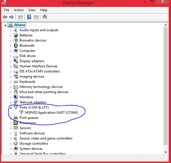
If you do not find the board discovered, go to the below Energia driver’s link and install the appropriate drivers.
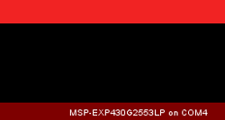
Once your board is discovered, make a note to which COM port it is connected to. Mine is connected to Port 4 here. Then go back to the Energia IDE and select Tools -> Port and select the same port I have select COM4 for me. Then again go to Tools -> Boards and select the MSP-EXP430G2553LP. Once done you should notice the following at the bottom right corner of your Energia IDE.
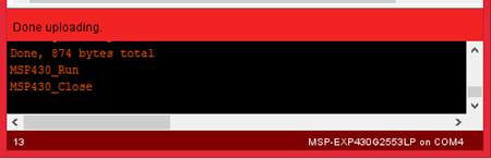
Now click on the upload icon on the top left corner (use the video at the bottom of this page if you are an absolute beginner) and your program should start uploading to your board. If everything works fine you should notice the “Done uploading” message appearing on your IDE as shown below
If otherwise, you might get the common error called “unable to find a device matching 0451:f432”. Follow the next step if you get this error, else proceed to verifying the output.
Unable to find a device matching 0451:f432 [Solution]:
This Error is very common with the Energia IDE but luckily there is a permanent solution for this that could be found at this forum thread.
I have also attached a video at the bottom of this page to show you how to resolve this problem. I you are not a big fan of videos then simply follow the steps below.
- copy <energia directory>\hardware\tools\DSLite\DebugServer\drivers\MSP430.dll to <energia directory>\hardware\tools\msp430\bin\
- edit <energia directory>\hardware\energia\msp430\boards.txt an change the 2 occurrences of rf2500 with tilib
- restart energia and you should be able to upload to the MSP-EXP430G2 with MSP430G2553.
Verifying our Blink Output:
Once the program is uploaded you can notice the Red LED on your Board blinking with a delay of 1000mS (1 sec) as programmed from our Energia IDE as shown below.
You can also verify the same using the video below that shows how I got the output. If everything has worked out till now, then give yourself a cookie and gear up for the next tutorial for more exciting stuff.
Hope you understood the tutorial and learned something useful if you got stuck anywhere please feel free to use the comment section below or the forums to post your questions and I would be happy to help you out.
Complete Project Code
#define LED RED_LED
// the setup routine runs once when you press reset:
void setup() {
  pinMode(LED, OUTPUT);     // initialize the digital pin as an output.
}
// the loop routine runs over and over again forever:
void loop() {
  digitalWrite(LED, HIGH);   // turn the LED on (HIGH is the voltage level)
  delay(1000);               // wait for a second
  digitalWrite(LED, LOW);    // turn the LED off by making the voltage LOW
  delay(1000);               // wait for a second
}
Superb description !!