

PIC Microcontrollers are a powerful platform provided by microchip for embedded projects; its versatile nature has enabled it to find ways into many applications and is yet to grow a lot. If you have been following our PIC tutorials then you would have noticed we have already covered a wide range of tutorials on PIC microcontroller starting from the very basics. In the same flow we are proceeding to learn the communication protocols available with PIC and how to use them. We have already covered I2C with PIC Microcontroller.
In the vast system of embedded applications, no microcontroller can perform all the activities by itself. At some stage of time it has to communicate to other devices to share information, there are many different types of communication protocols to share these information’s, but the most used ones are USART, IIC, SPI and CAN. Each communication protocol has its own advantage and disadvantage. Let’s focus on the SPI Protocol for now since that is what we are going to learn in this tutorial.
What is SPI Communication Protocol?
The term SPI stands for “Serial Peripheral Interface”. It is a common communication protocol that is used to send data between two microcontrollers or to read/write data from a sensor to a microcontroller. It is also used to communicate with SD cards, shift registers, Display controllers and much more.
How SPI Protocol Works?
The SPI communication is synchronous communication, meaning it works with the help of a clock signal which is shared between the two devices that are exchanging the data. Also it a full-duplex communication because it can send and receive data using a separate bus. The SPI communication requires 5 wires to operate. A simple SPI communication circuit between a master and slave is shown below
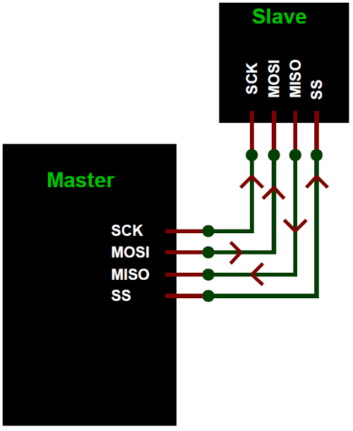
The five wires required for the communication are SCK (Serial Clock), MOSI (Master Out Slave In), MISO (Master In Slave Out) and SS (Slave Select). The SPI communication always takes places only between a master and slave. A master can have multiple slaves connected to it. The master is responsible for generating the clock pulse and the same is shared with all slaves. Also all communications can be initiated only by the master.
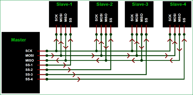
The SCK pin (a.k.a SCL-serial clock) shares the clock signal generates by the master with the slaves. The MOSI pin (a.k.a SDA –Serial Data Out) is used to send the data from the master to the salve. The MISO pin (a.k.a SDI – Serial Data In) is used to get the data from the salve to the master. You can also follow the arrow mark in the above figure to understand the movement of data/signal. Finally the SS pin (a.k.a CS –Chip select) is used when there are more than one slave modules connected to the master. This in can be used to select the required slave. A sample circuit where more than one slave is connected with the master for SPI communication is shown in the circuit below.
Difference between I2C and SPI Communication
We have already learnt I2C communication with PIC and so we must be familiar with how I2C works and where we can use them like I2C can be used to interface RTC module. But now, why do we need SPI protocol when we already have I2C. The reason is both I2C and SPI communications are advantages in its own ways and hence is application specific.
To an extent the I2C communication can be considered to have some advantages over SPI communication because I2C uses less number of pin and it gets very handy when there are a large number of slaves connected to the bus. But the drawback of I2C is that it has the same bus for sending and receiving data and hence it is comparatively slow. So it’s purely based on application to decide between SPI and I2C protocol for your project.
SPI with PIC16F877A using XC8 Compiler:
Enough of basics, now let us learn how we can use SPI communication on the PIC16F877A microcontroller using the MPLABX IDE and XC8 compiler. Before we start make it clear that this tutorial only talks about SPI in PIC16F877a using XC8 compiler, the process will be the same for other microcontrollers but slight changes might be required. Also remember that for advanced microcontrollers like the PIC18F series the compiler itself might have some library in-built to use the SPI features, but for PIC16F877A nothing like that exists so let’s build one on our own. The library explained here will be given as a header file for download at the bottom which can be used for PIC16F877A to communicate with other SPI devices.
In this tutorial we will write a small program that uses SPI communication to write and read data from the SPI bus. We will then verify the same using Proteus simulation. All the code related to SPI registers will be made inside the header file called PIC16f877a_SPI.h. This way we can use this header file in all our upcoming projects in which SPI communication is required. And inside the main program we will just use the functions from the header file. The complete code along with the header file can be downloaded from here.
SPI Header File Explanation:
Inside the header file we have to initialize the SPI communication for PIC16F877a. As always the best place to start is the PIC16F877A datasheet. The registers which control the SPI communication for PIC16F8777a is the SSPSTAT and the SSPCON Register. You can read more about them on page 74 and 75 of the datasheet.
There are many parameters options that has to be chosen while initializing the SPI communication. The most commonly used option is the clock frequency will be set to Fosc/4 and will be done in the middle and the clock will be set as low at ideal state. So we are also using the same configuration for our header file, you can easily change them by changing the respective bits.
SPI_Initialize_Master()
The SPI initialize Master function is used to start the SPI communication as the master. Inside this function we set the respective pins RC5 and RC3 as output pins. Then we configure the SSPTAT and the SSPCON register to turn on the SPI communications
void SPI_Initialize_Master()
{
TRISC5 = 0; //
SSPSTAT = 0b00000000; //pg 74/234
SSPCON = 0b00100000; //pg 75/234
TRISC3 = 0; //Set as output for slave mode
}
SPI_Initialize_Slave()
This function is used to set the microcontroller to work in slave mode for SPI communication. During slave mode the pin RC5 should be set as output and the pin RC3 should be set as input. The SSPSTAT and the SSPCON is set in the same way for both the slave and the master.
void SPI_Initialize_Slave()
{
     TRISC5 = 0; // SDO pin should be declared as output
     SSPSTAT = 0b00000000; //pg 74/234
     SSPCON = 0b00100000; //pg 75/234
     TRISC3 = 1; //Set as in out for master mode
}
SPI_Write(char incoming)
The SPI Write function is used to write data into the SPI bus. It gets the information from the user through the variable incoming and then uses it to pass to the Buffer register. The SSPBUF will be cleared in the consecutive Clock pulse and the data will sent into the bus bit by bit.
void SPI_Write(char incoming)
{
    SSPBUF = incoming; //Write the user given data into buffer
}
SPI_Ready2Read()
The SPI ready to Read function is used to check if the data in the SPI bus is received completely and if it can be read. The SSPSTAT register has a bit called BF which will set once the data has been received completely, so we check if this bit is set if it is not set then we have to wait till it gets set to read anything from the SPI bus.
unsigned SPI_Ready2Read()
{
    if (SSPSTAT & 0b00000001)
        return 1;
    else
        return 0;
}
SPI_Read()
The SPI Read is used to read the data from the SPI bus into the microcontroller. The data present in the SPI bus will be stored in the SSPBUF, we have to wait till the complete data is stored in the Buffer and then we can read it into a variable. We check the BF bit of SSPSTAT register before reading the buffer to make sure the data reception is complete.
char SPI_Read() //Read the received data
{
    while ( !SSPSTATbits.BF ); // Hold till BF bit is set, to make sure the complete data is read
    return(SSPBUF); // return the read data
}

Main program Explanation:
The functions explained in the above section will be in the header file and they can be called into the main c file. So let’s write a small program to check if the SPI communication is working. We will just write few data into the SPI bus and use the proteus simulation to check if the same data is being received in the SPI debugger.
As always begin the program by setting the configuration bits and then it is very important to add the header file that we just explained into the program as shown below
#include <xc.h>
#include "PIC16F877a_SPI.h"
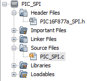
If you have opened the program from the zip file downloaded above then by default the header file will be present inside the header file directory of your project file. Else you have to add the header file manually inside your project, once added your project files will look like this below
Inside the main file we have to initialize the PIC as Master for SPI communication and then inside an infinite while loop we will write random three hex values into the SPI bus to check if we receive the same during simulation.
void main()
{
   SPI_Initialize_Master();

   while(1)
   {
       SPI_Write(0X0A);
         __delay_ms(100);
       SPI_Write(0X0F);
         __delay_ms(100);
       SPI_Write(0X15);
         __delay_ms(100);
   }
}
Notice that the random values used in the program are 0A, 0F and 15 and they are hex values so we should see the same during simulation. That is it the code is all done, this is just a sample but we can use the same methodology to communicate with other MCU or with other sensors module operating on SPI protocol.
Simulating PIC with SPI debugger:
Now that our program is ready we can compile it and then proceed with simulation. Proteus has a nice handy feature called SPI debugger, which can be used to monitor the data over an SPI bus. So we use the same and build a circuit like shown below.

Since there is only one SPI device in the simulation we are not using the SS pin and when not used it should be grounded as shown above. Just load the hex file into the PIC16F877A microcontroller and click on the play button to simulate our program. Once the simulation starts you will get a pop-up window which displays the data in the SPI bus as shown below
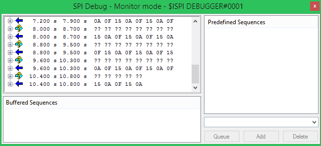
Let’s take a closer look at the data coming in and check if it is the same as the one that we wrote in our program.

The data is received in the same order that we wrote in our program and the same is highlighted for you. You can also try simulating a program to communicate with two PIC microcontrollers using SPI protocol. You have to program one PIC as the master and the other as the slave. All the required header files for this purpose are given in the header file already.
This is just a glimpse of what SPI can do, it can also read and write data to multiple devices. We will cover more about SPI in our upcoming tutorials by interfacing various modules that work with SPI protocol.
Hope you understood the project and learnt something useful from it. If you have any doubts post them in the comment section below or use the forums for technical help.
Complete Main code has been given below; you can download header files with all the code from here
Complete Project Code
/*
 * File:   PIC_SPI.c
 * Author: Aswinth
 *
 * Created on 15 May, 2018, 1:46 PM
 */
// CONFIG
#pragma config FOSC = XT   // Oscillator Selection bits (XT oscillator)
#pragma config WDTE = OFF  // Watchdog Timer Enable bit (WDT disabled)
#pragma config PWRTE = OFF // Power-up Timer Enable bit (PWRT disabled)
#pragma config BOREN = OFF // Brown-out Reset Enable bit (BOR disabled)
#pragma config LVP = OFF   // Low-Voltage In-Circuit Serial Programming Enable bit
#pragma config CPD = OFF   // Data EEPROM Memory Code Protection bit
#pragma config WRT = OFF   // Flash Program Memory Write Enable bits
#pragma config CP = OFF    // Flash Program Memory Code Protection bit
#include <xc.h>
#include "PIC16F877a_SPI.h"
#define _XTAL_FREQ 20000000
void main()
{
   SPI_Initialize_Master();
   while(1)
   {
       SPI_Write(0X0A);
         __delay_ms(100);
       SPI_Write(0X0F);
         __delay_ms(100);
       SPI_Write(0X15);
         __delay_ms(100);
   }
}
Comments
hi friend please can you…
hi friend
please can you help me to establish an SPI interface with pic16f877a and nokia-5110.
I have downloaded your 16f877a SPI header file and would also try to display image on the lcd.
I thank you

Hi friend,
Can you make tutorials about heart rate sensor and/or accelerometer for PIC? Of course, if enough people want the same. I studying Biomedical engineering and we can use that informations for various interesting projects.
Greetings from Serbia