
In previous tutorials we have seen How we can build an Amazon Echo Speaker and then how can we control any Raspberry Pi GPIO using Alexa Voice. Now we are making an IoT project to control home appliances from anywhere in the world using AlexaPi and ESP-12E (or any ESP board).
Hardware Requirements
- Raspberry Pi with AVS installed in it
- USB 2.0 mic /Webcam
- ESP-12E
- Relay module
- LED/AC bulb
You should have your Raspberry Pi ready with Alexa voice service installed in it with a properly configured Amazon Developer Account. So go through below tutorial to get Alexa services ready.
Project Flow for Alexa Voice Controlled LED
We will follow this flowchart for this IoT controlled LED project:


So, the process is something like this. First, input is given to Raspberry Pi through the USB Mic. Now, this recording is sent to Alexa voice services and after voice recognition, AVS sent the data to IFTTT and it triggers the condition in IFTTT. According to the recipe, IFTTT will send the command to Adafruit IO which is the MQTT broker to perform an action. Then ESP12e will receive the data from Adafruit IO via MQTT protocol and LED will turn ON/OFF according to the command.
Here we have used a USB WebCam for Microphone. We have already used Alexa Voice service to turn on a bulb, but it can only handle appliances which are connected locally.
As we assume that you already have Raspberry Pi with Alexa Voice services installed, so we are remaining with below two steps, which we will explain one by one:
- Setting Up an Adafruit account for communication
- Link Alexa to Adafruit IO using IFTTT
- Upload code in ESP12
Setting Up an Adafruit account for communication
First, we will make a feed in Adafruit IO. Feed stores the data sent by IFTTT. To make feed follow these steps:
Step 1:- Login to Adafruit IO with your credentials or Sign up if you don’t have an account.

Step 2:-Click on My account -> Dashboard
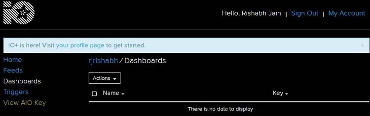
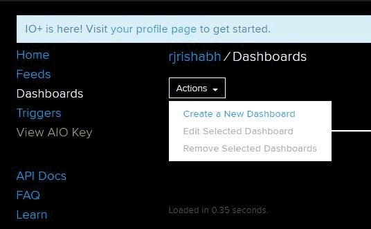
Step 3:-Click on Actions and Create a New Dashboard.
Step 4:-Give name and description to your feed and click on Create.

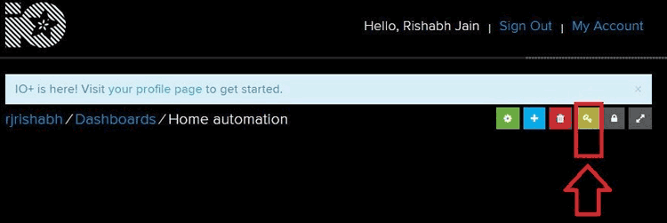
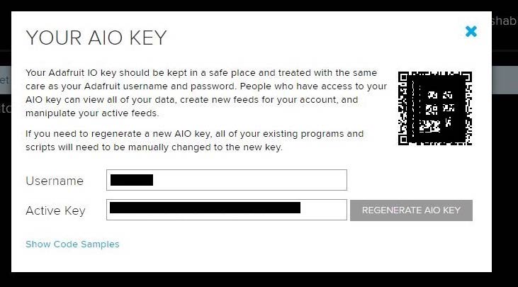
Step 5:-Click on Key button and note down the AIO Keys, we will use this key in our code.
Step 6:-Click on ‘+’ button to create a new block and click on Toggle button.

Step 7:-Now, Enter Name of Feed and click on Create. Then Select the feed and click on Next step.

Step 8:-In block settings, Write ‘1’ in Button ON text field and ‘0’ in Button OFF Text field.

Step 9:-Your Feed is successfully created.

Link Alexa to Adafruit IO using IFTTT
Follow these steps to make an Applet/Recipe in IFTTT:
Step 1:- Login to IFTTT with your credentials or Sign Up if you don’t have an account on it.
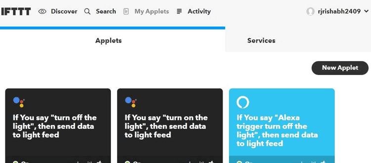
Step 2:- On My Applets, Click on New Applet
Step 3:- Click on +this
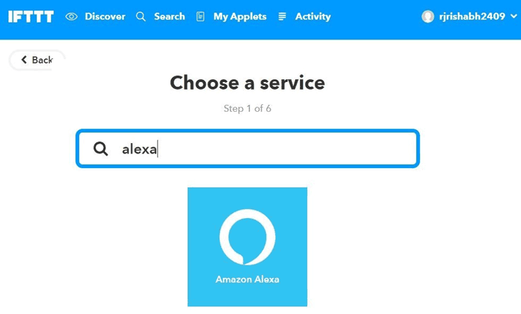
Step 4:- Search Amazon Alexa and click on it, sign in with your amazon developer account details.
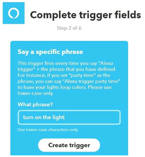
Step 5:- Choose the trigger, Say a specific phrase
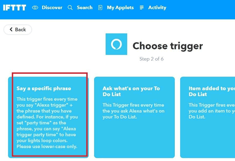
Step 6:- Provide “turn on the light” as the phrase, click on Create Trigger.
Step 7:- Click on +that

Step 8:-Search Adafruit and click on it.

Step 9:-Login to Adafruit Account using your credentials. Click on Send data to Adafruit.
Select feed name that you just created in Adafruit IO. Now, give ‘1’ in data to save, this implies LED will be ON. Click on Create Action.

Step 10:-Follow the same steps to make applets to turn the LED OFF. Just put ‘0’ in the Data to save field. All steps remain the same.
You have done half of your work. Now, it’s time to program your ESP-12E.
ESP12 Code Explanation
We will program ESP12 with Arduino IDE. Complete code is given at the end of this Tutorial.
First, we need a Adafruit Mqtt library which can be downloaded from this link. Just open Arduino IDE . Go to examples -> adafruit mqtt library -> mqtt_esp8266

We will edit this code according to our AIO keys and Wi-Fi credentials.
First, we included all the libraries for ESP8266WIFI and Adafruit MQTT.
#include <ESP8266WiFi.h>
#include "Adafruit_MQTT.h"
#include "Adafruit_MQTT_Client.h"
We defined the SSID and Password for your Wi-Fi, from which you want to connect your ESP-12e.
#define WLAN_SSID       "xxxxxxxx"
#define WLAN_PASS       "xxxxxxxxxxx"
This section defines the Adafruit server and server port which is fixed as “io.adafruit.com” and “1883” respectively.
#define AIO_SERVER      "io.adafruit.com"
#define AIO_SERVERPORT  1883
Replace below fields with your username and AIO keys which you have copied from Adafruit site while making the Feed.
#define AIO_USERNAME    "********"
#define AIO_KEY         "******************************"
Then create an ESP8266 WiFiClient class to connect to the MQTT server.
WiFiClient client;
Setup the MQTT client class by passing in the WiFi client and MQTT server and login details.
Adafruit_MQTT_Client mqtt(&client, AIO_SERVER, AIO_SERVERPORT, AIO_USERNAME, AIO_KEY);
Setup a feed called 'light' for subscribing to changes.
Adafruit_MQTT_Subscribe light = Adafruit_MQTT_Subscribe(&mqtt, AIO_USERNAME "/feeds/light");
In setup function, we declare PIN of ESP-12e on which you want to get output. I am using D0 pin as output. Then, we connect ESP-12e to Wi-fi access point.
void setup() {
  Serial.begin(115200);
  delay(10);
  pinMode(D0, OUTPUT);
  Serial.println(F("Adafruit MQTT demo"));
  // Connect to WiFi access point.
  Serial.println(); Serial.println();
  Serial.print("Connecting to ");
  Serial.println(WLAN_SSID);
  WiFi.begin(WLAN_SSID, WLAN_PASS);
  while (WiFi.status() != WL_CONNECTED) {
….
….
…
Setup MQTT subscription for light feed.
  mqtt.subscribe(&light);

}
In loop function, we will ensure that the connection to the MQTT server is alive using MQTT_connect(); function.
void loop() {
  MQTT_connect();
Now, we subscribe our ‘light’ feed and get the string from adafruit IO and convert this string to number using atoi(); function and write this number to PIND0 using digitalWrite(); function.
  Adafruit_MQTT_Subscribe *subscription;
  while ((subscription = mqtt.readSubscription(5000))) {
    if (subscription == &light) {
      Serial.print(F("Got_light: "));
      Serial.println((char *)light.lastread);
      uint16_t num = atoi((char *)light.lastread);
      digitalWrite(16,num);
    }

Working:
Connect your ESP-12E with the laptop and upload below code (don’t forget to edit your credentials in the code).
Connect a LED or relay to pin D0. Now, make sure your Alexa service is running on your RPi.

To give any command you need to wake up Alexa service by calling “Alexa” each time you want to send a command. You will hear a beep sound. Once you hear the beep, say “Alexa Trigger Turn on the Light.” You can see the light turns ON within a moment. And then if you say “Alexa Trigger Turn off the Light”, the light should turn OFF.
That’s it…. You can add more appliances in the above code by adding the GPIO pins of ESP-12E and by making different Applets with different phrases in IFTTT.
Check the complete code and Demonstration Video below. Also check our all the Home Automation Projects here
Complete Project Code
#include <ESP8266WiFi.h>

#include "Adafruit_MQTT.h"

#include "Adafruit_MQTT_Client.h"
#define WLAN_SSID       "**********"

#define WLAN_PASS       "**********"

#define AIO_SERVER      "io.adafruit.com"

#define AIO_SERVERPORT  1883

#define AIO_USERNAME    “**********"

#define AIO_KEY         "**********************"

Adafruit_MQTT_Client mqtt(&client, AIO_SERVER, AIO_SERVERPORT, AIO_USERNAME, AIO_KEY);
Adafruit_MQTT_Subscribe light = Adafruit_MQTT_Subscribe(&mqtt, AIO_USERNAME "/feeds/light");
void MQTT_connect();
void setup() {

  Serial.begin(115200);

  delay(10);

  pinMode(D0, OUTPUT);
  Serial.println(F("Adafruit MQTT demo"));
  // Connect to WiFi access point.

  Serial.println(); Serial.println();

  Serial.print("Connecting to ");

  Serial.println(WLAN_SSID);
  WiFi.begin(WLAN_SSID, WLAN_PASS);

  while (WiFi.status() != WL_CONNECTED) {

    delay(500);

    Serial.print(".");

  }

  Serial.println();
  Serial.println("WiFi connected");

  Serial.println("IP address: "); Serial.println(WiFi.localIP());
  // Setup MQTT subscription for light feed.

  mqtt.subscribe(&light);

}
uint32_t x=0;
void loop() {

  MQTT_connect();
  Adafruit_MQTT_Subscribe *subscription;

  while ((subscription = mqtt.readSubscription(5000))) {

    if (subscription == &light) {

      Serial.print(F("Got_light: "));

      Serial.println((char *)light.lastread);

      uint16_t num = atoi((char *)light.lastread);

      digitalWrite(D0,num);

    }

  }
void MQTT_connect() {

  int8_t ret;
  // Stop if already connected.

  if (mqtt.connected()) {

    return;

  }
  Serial.print("Connecting to MQTT... ");
  uint8_t retries = 3;

  while ((ret = mqtt.connect()) != 0) { // connect will return 0 for connected

       Serial.println(mqtt.connectErrorString(ret));

       Serial.println("Retrying MQTT connection in 5 seconds...");

       mqtt.disconnect();

       delay(5000);  // wait 5 seconds

       retries--;

       if (retries == 0) {

         // basically die and wait for WDT to reset me

         while (1);

       }

  }

  Serial.println("MQTT Connected!");

}
Comments
nice post its helpful
Hey I have been following your tutorial and everything is working just fine except the IFTTT part. I have created the applet correctly and adafruit IO is also working fine but Alexa ends up replying 'I don't see that IFTTT trigger', Any help would be highly appreciated.

I think this post very useful to so many people.
So I really thank you for your help.