
Security is a major concern in our day to day life, and digital locks have become an important part of these security systems. There are many types technologies available to secure our place, like PIR Based security systems, RFID based Security system, Laser security alarms, bio-matrix systems etc. Even now, there are Digital locks which can be operated using our smart phones, means no more need to keep different keys, just one smart phone can operate all the locks, this concept is based on Internet of Things.
In this project, we have explained a simple Electronic code lock using 8051 Microcontorller, which can only be unlocked by a predefined code, if we enter the wrong code, the system alerts by siren the buzzer. We have already created a Digital lock using Arduino.
Working Explanation:
This system mainly contains AT89S52 microcontroller, keypad module, buzzer and LCD. At89s52 microcontroller controls the complete processes like taking password form keypad module, comparing passwords predefined password, driving buzzer and send status to LCD display. Keypad is used for inserting password into the microcontroller. Buzzer is used for indication of wrong password and LCD is used for displaying status or messages on it. Buzzer has inbuilt driver by using a NPN transistor.
Components:
- 8051 Microcontroller (AT89S52)
- 4X4 Keypad Module
- Buzzer
- 16x2 LCD
- Resistor (1k,10k)
- Pullup resistor (10K)
- Capacitor(10uf)
- Red led
- Bread board
- IC 7805
- 11.0592 MHz Crystal
- Power Supply
- Connecting wires
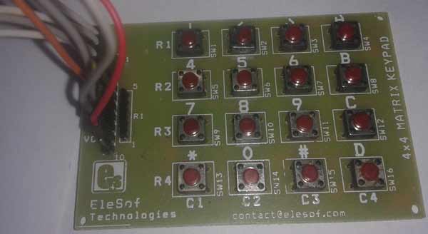
Taking input from 4X4 Keypad Matrix using Multiplexing Technique:
In this circuit we have used multiplexing technique to interface keypad to the 8051 microcontroller, for entering the password in the system. Here we are using a 4x4 keypad which has 16 keys. If we want to use 16 keys then we need 16 pin for connection to 89s52, but in multiplexing technique we need to use only 8 pins for interfacing 16 keys. So that it is a smart way to interface the keypad module.
Multiplexing technique is a very efficient way to reduce number of pins used with the microcontroller for providing the input or password. Basically this technique is used in two ways - one is row scanning and other one is column scanning.
Here we are going to explain row scanning:
First we have to define 8 pin for keypad module. In which first 4 pins are column and last 4 pins are rows.
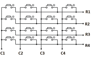
For row scanning we need to give data or signal to column pins and read that data or signal from row pin. Now suppose we give below data to column pins:
C1=0;
C2=1;
C3=1;
C4=1;
And we read this data at row pins (by default row pins are HIGH due to pull-up resistor).
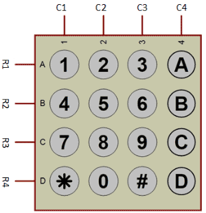
If user presses key number ‘1’ then R1 changes HIGH to LOW means R1=0; and controller understands that user has pressed key ‘1’. And it will print ‘1’ on the LCD and store ‘1’ in array. So this HIGH to LOW change at R1, is the main thing by which controller understands that some key, corresponding to Column 1, has been pressed.
Now if user presses key number ‘2’ then R1 remains at HIGH as C1 and R1 both are already at HIGH. Hence there will be no change, it means microcontroller understands that nothing has been pressed in column one. And likewise this principal goes for all another pins. So in this step controller only waits for keys in column one: ‘1’, ‘4’, ‘7’ and ‘*’.
Now if we want to track the keys in other columns (like in col 2), then we need to change the data at columns pins:
C1=1;
C2=0;
C3=1;
C4=1;
This time controller only waits for keys in column two: ‘2’, ’5’, ’8’and ‘0’, because change (HIGH to LOW) only occurs when column two keys will be pressed. If we press any key in col 1, 3 or 4 then no change will occur, because these columns are at HIGH, and Rows are already at HIGH.
So likewise keys in column C3 and C4 can also be tracked by making them 0, at a time. Check here the detailed explanation: Keypad Interfacing with 8051. Also go through the Code section below for properly understand the logic.
Circuit Explanation:
Circuit diagram for this Digital lock using 8051 has been shown below and can easily be understood. Keypad module’s Column pins are directly connected to pin P0.0, P0.1, P0.2, P0.3 and Row pins are connected to P0.4, P0.5, P0.6, P0.7 of 89s52 microcontroller’s port 0. A 16x2 LCD is connected with 89s52 microcontroller in 4-bit mode. Control pin RS, RW and En are directly connected to pin P1.0, GND and P1.2. And data pin D4-D7 is connected to pins P1.4, P1.5, P1.6 and P1.7 of 89s52. And one buzzer is connected at pin P2.6 through a resistor.

Program Explanation:
We have used a predefined password in the program, this password can be defined by the user in the code below. When user enters a password to the system, then system compares the user entered password with stored or predefined password in Code of Program. If a match occurs then LCD will show “Access Grated” and if the password doesn’t match then LCD will show “Access Denied” and buzzer will continuously beep for some time. Here we have used string.h library. By using this library we can compare or match two strings, by using “strncmp” function.
In the program, first of all we include header file and defines variable and input & output pins for keypad and LCD.
#include<reg51.h>
#include<string.h>
#define lcdport P1
sbit col1=P0^0;
sbit col2=P0^1;
sbit col3=P0^2;
sbit col4=P0^3;
sbit row1=P0^4;
sbit row2=P0^5;
sbit row3=P0^6;
sbit row4=P0^7;
sbit rs=P1^0;
sbit en=P1^2;
sbit buzzer=P2^6;
Function for creating the delay of 1 second has been created, along with some LCD functions like for LCD initialization, printing the string, for commands etc. You can easily find them in Code. Check this article for LCD interfacing with 8051 and its functions.
After this, in main program we have initialize LCD and then we read the input from Keypad using the keypad() function and stores input keys into an array and then compare it from predefined array data using strncmp.
void main()
{
    buzzer=1;
    lcd_init();
    lcdstring("Electronic Code");
    lcdcmd(0xc0);
    lcdstring("  Lock System  ");
    delay(400);
    lcdcmd(1);
    lcdstring("Circuit Digest");
    delay(400);
    while(1)
    {
            i=0;
            keypad();
            if(strncmp(pass,"4201",4)==0)
If entered password is matched, then accept() function is called:
void accept()
{
     lcdcmd(1);
     lcdstring("Welcome");
     lcdcmd(192);
     lcdstring("Password Accept");
     delay(200);
}
And if password is wrong then wrong() function is called:
void wrong()
{
    buzzer=0;
    lcdcmd(1);
     lcdstring("Wrong Passkey");
    lcdcmd(192);
    lcdstring("PLZ Try Again");
    delay(200);
    buzzer=1;
}
Check the keypad function below in the code which reads the input form keypad module.
Complete Project Code
#include<reg51.h>
#include<string.h>
#define lcdport P1
sbit col1=P0^0;
sbit col2=P0^1;
sbit col3=P0^2;
sbit col4=P0^3;
sbit row1=P0^4;
sbit row2=P0^5;
sbit row3=P0^6;
sbit row4=P0^7;
sbit rs=P1^0;
sbit en=P1^2;
sbit buzzer=P2^6;
char pass[4],i=0;
void delay(int itime)
{
    int i,j;
    for(i=0;i<itime;i++)
    for(j=0;j<1275;j++);
}
void daten()
{
    rs=1;
    en=1;
    delay(5);
    en=0;
}
void lcddata(unsigned char ch)
{
    lcdport=ch & 0xf0;
    daten();
    lcdport=(ch<<4) & 0xf0;
    daten();
}
void cmden(void)
{
    rs=0;
    en=1;
    delay(5);
    en=0;
}
void lcdcmd(unsigned char ch)
{
    lcdport=ch & 0xf0;
    cmden();
    lcdport=(ch<<4) & 0xf0;
    cmden();
}
void lcdstring(char *str)
{
    while(*str)
    {
        lcddata(*str);
        str++;
    }
}
void lcd_init(void)
{
    lcdcmd(0x02);
    lcdcmd(0x28);
    lcdcmd(0x0e);
    lcdcmd(0x01);
}

void keypad()
{
        int cursor=192,flag=0;
    lcdcmd(1);
    lcdstring("Enter Ur Passkey");
    lcdcmd(0xc0);
    i=0;
    while(i<4)
    {
    flag=cursor;
     col1=0;
     col2=col3=col4=1;
     if(!row1)
     {
        lcddata('1');
        pass[i++]='1';
        cursor++;
        while(!row1);
          }

      else if(!row2)
     {
        lcddata('4');
        pass[i++]='4';
        cursor++;
        while(!row2);
        }

      else if(!row3)
     {
        lcddata('7');
        pass[i++]='7';
        cursor++;
        while(!row3);
        }

      else if(!row4)
     {
        lcddata('*');
        pass[i++]='*';
        cursor++;
        while(!row4);
        }

     col2=0;
     col1=col3=col4=1;
     if(!row1)
     {
        lcddata('2');
        pass[i++]='2';
        cursor++;
        while(!row1);
        }

      else if(!row2)
     {
        lcddata('5');
        pass[i++]='5';
        cursor++;
        while(!row2);
        }

      else if(!row3)
     {
        lcddata('8');
        pass[i++]='8';
        cursor++;
        while(!row3);
        }

      else if(!row4)
     {
        lcddata('0');
        pass[i++]='0';
        cursor++;
        while(!row4);
        }

     col3=0;
     col1=col2=col4=1;
     if(!row1)
     {
        lcddata('3');
        pass[i++]='3';
        cursor++;
        while(!row1);
        }

      else if(!row2)
     {
        lcddata('6');
        pass[i++]='6';
        cursor++;
        while(!row2);
        }

      else if(!row3)
     {
        lcddata('9');
        pass[i++]='9';
        cursor++;
        while(!row3);
        }

      else if(!row4)
     {
        lcddata('#');
        pass[i++]='#';
        cursor++;
        while(!row4);
        }

      col4=0;
     col1=col3=col2=1;
     if(!row1)
     {
        lcddata('A');
        pass[i++]='A';
        cursor++;
        while(!row1);
        }

      else if(!row2)
     {
        lcddata('B');
        pass[i++]='B';
        cursor++;
        while(!row2);
        }

      else if(!row3)
     {
        lcddata('C');
        pass[i++]='C';
        cursor++;
        while(!row3);
        }

      else if(!row4)
     {
        lcddata('D');
        pass[i++]='D';
        cursor++;
        while(!row4);
          }
     if(i>0)
     {
         if(flag!=cursor)
         delay(100);
         lcdcmd(cursor-1);
         lcddata('*');
     }
 }
}
void accept()
{
     lcdcmd(1);
     lcdstring("Welcome");
     lcdcmd(192);
     lcdstring("Password Accept");
     delay(200);
}
void wrong()
{
    buzzer=0;
    lcdcmd(1);
     lcdstring("Wrong Passkey");
    lcdcmd(192);
    lcdstring("PLZ Try Again");
    delay(200);
    buzzer=1;
}
void main()
{
    buzzer=1;
    lcd_init();
    lcdstring("Electronic Code");
    lcdcmd(0xc0);
    lcdstring("  Lock System  ");
    delay(400);
    lcdcmd(1);
    lcdstring("Circuit Digest");
    delay(400);
    while(1)
    {
            i=0;
            keypad();
            if(strncmp(pass,"4201",4)==0)
            {
            accept();
            lcdcmd(1);
            lcdstring("Access Granted ");
            delay(300);
                }

        else
        {
           lcdcmd(1);
           lcdstring("Access Denied");
           wrong();
           delay(300);
        }
    }
}
Comments
Hi guys im currently doing a project on a security system using the microntroller 8051 , and wanted to try the code to demo . But when i run my code on Silicon IDE , the code is able to be build and download into the microntroller . But the LCD doesnt seem to light up with the Enter The Password for me to type input the password . Can you guys help me out .
thanks mason
Please can someone help me with assembly language code for door lock password system
can you add servo motor in th project for lock the doar
How can i generate the assembly language code of the code above given and using which software?
please help me.
Hi there,
This is an interesting project.Please tell me, can I use hash function to check the parity bits in this project? If yes then how?
Thanks.
can 8051 be programmed in basic.

very interesting