
You have seen street light which automatically gets turned on in the night and gets turned off in the morning or day time, there are sensors who senses the light and control the light accordingly. These Street lights are an important project in smart cities.
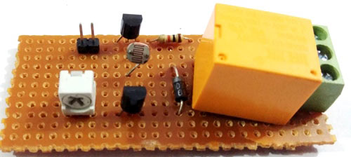
So here in this project, we are going to make a Simple Automatic Street Light Circuit using LDR and Relay, which will turn on and off the light bulb based on the lights in surroundings. This circuit is quite simple and can be built with Transistors and LDR, you don’t need any op-amp or 555 IC to trigger the AC load. Here we have used an AC bulb as street light. Some applications of this circuit are street light controlling, home/office light controlling, day and night indicators, etc.
Components Required:
- Transistor BC547 -2
- LDR (Light Dependent Resistor)
- Relay
- Resistor 1k
- 100k Potentiometer
- Power Supply 12v -1
- Connecting wires
- Jumper wires
- Screw terminal Block 2 pin or 3 pin
- Bread Board or Perf Board
- 1n4007 Diode
- AC supply
- AC Load or Bulb
What is LDR?
LDRs are made from semiconductor materials to enable them to have their light sensitive properties. There are many types but one material is popular and it is cadmium sulphide (CdS). These LDRs or PHOTO REISTORS works on the principle of “Photo Conductivity”. Now what this principle says is, whenever light falls on the surface of the LDR (in this case) the conductance of the element increases or in other words the resistance of the LDR falls when the light falls on the surface of the LDR. This property of the decrease in resistance for the LDR is achieved because it is a property of semiconductor material used on the surface.
")
Previously we have built many useful circuits using the LDR, you can find few of the popular LDR circuit projects below.
- Dark Detector using LDR and 555 Timer IC
- Dark and Light Indicator Circuit
- Simple LDR Circuit
- Automatic Staircase Light
- Laser Security Alarm Circuit
Circuit Diagram and Explanation:
Below is the circuit diagram of this Light sensing Street Light project.

In this project, we have used an LDR (Light Dependent Resistor) which is responsible for detecting light and darkness. The resistance of LDR increases in darkness and reduces in presence of light. This circuit is same as a Dark Detector or Light Detector Circuit, only here we have replaced simple LED with a AC load, using a Relay. Two BC547 NPN transistors are used to drive the relay.
Whenever light falls over LDR its resistance get decreased and transistor Q1 turns ON and collector of this transistor goes LOW, and this makes the second transistor turns OFF due to getting a LOW signal at its base, so relay also remain turned OFF due to second transistor.
Now whenever LDR senses Darkness, mean no light, then transistor Q1 turned ON due to increase in the resistance of LDR which is responsible for voltage drop at the base of Q1. Due to a LOW signal at the Q1 base, Q2 transistor gets a HIGH signal from the collector of Q1 and turns ON the relay. Relay turned ON the AC load that is connected to relay. A 10K pot is also used for setting up the sensitivity of the circuit.
So this is how automatic Street Lights turns on in the night and turn off in the day, check the Demonstration Video below.
Comments
Sir, can I copy this in my project please?? ineed ur code ....please help me..
Can u pls show me the code?
This project does not have any code. You can use the circuit diagram above and make the connections and it will start working straight away
Please, AISHA.
I'm a student of electrical engineering in Kano University of science and technology, wudil. In Nigeria. If you can please help me send me the full write-up of this project "automatic street light control system module using ac source"
Thank you here is my email address: usmanmukhtar1000@gmail.com
it goes light on while making power on.
Can I use their LM358 or comperator.if I can do that then how is it works?
Automatic street light
Please tell me the details about the relay we use in this circuit.

Can I use 2n2222 transistor instead of bc547