
")
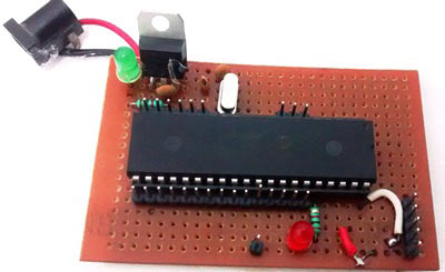
In our previous tutorial, we learnt about Blinking a LED using PIC microcontroller and built the same circuit on Perf board. Then we used PICkit 3, ICSP and MPLAB IPE for dumping the program onto our Perf board. Now, in this tutorial we will advance our self to using more pins on the PIC microcontroller. We will use 7 outputs (LEDs) and one Input. For this tutorial we will use the old Perf board (shown below) and will add berg sticks to pull out the required pins onto the second LED board. At the end of this tutorial we will Generate a Sequence of Blinking LEDs using PIC microcontroller PIC16F877A and will learn how to use multiple inputs and outputs, some basics on ‘for’ loop and function calling.
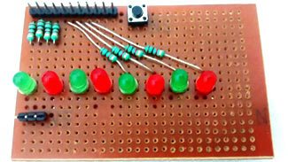
The LED board is nothing but another perf board, on which we will solder the LED's with a current limiting Resistor (shown below). We will also add a pushbutton to initiate the sequence LED blinking.
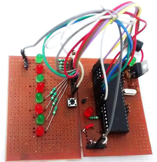
Circuit Diagram:

PIC Microcontroller PIC16F877A LED Blinking Sequence Code and Working Explanation:
Complete Code has been given below (check at the end), here we will get it through line by line. This code will start to glow LEDs in a sequential manner when the push button is pressed. In order to understand the sequences please watch the video at the end of the tutorial. I would recommend you to compare the output shown in video with the code below and try to understand the program.
Let’s look at the code line by line. The first few lines are for setting up configuration bits which were explained in the previous tutorial so I am skipping them for now. The best way to understand any program is to start from the main (void main ()) function, so let's do that
TRISB0=1; //Instruct the MCU that the PORTB pin 0 is used as input for button.
TRISD = 0x00; //Instruct the MCU that all pins are output
PORTD=0x00; //Initialize all pins to 0
The word TRIS is used to define if the pin is being used as input/output and the word PORT is used to make a pin High/Low. The line TRISB0=1 will make the 0th pin of PORT B as input. This will be our pushbutton. The lines TRISD = 0x00; PORTD=0x00; will make all the pins of port D as Output and assign a initial value of LOW to those pins.
Since we said that B0 is used as input, we will connect one end of the pushbutton to the pin B0 and other end to the ground. By then whenever we press the button the pin will be held to ground as shown in the connection diagram above. But to make this happen we have to use a pull up resistor so that the pin will be held high when the button is not pressed. A pull up resistor is something like this.
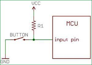
But our PIC MCU has an internal weak pull up resistor which can be activated by software that way saving a lot of hassle (when more buttons are to be connected).
What is a Weak pull up resistor?
There are two type of pull up resistor, one is Weak Pull Up and other is Strong Pull Up. The weak pull up resistors are of high value and thus allowing a weak current to flow through and the strong pull up resistors are of low value thus allowing a strong current to flow. All MCU mostly use weak pull up resistors. In order to activate this in our PIC MCU we have to look into our data sheet for the OPTION_REG (option register) as shown in the snapshot below.
As shown the bit 7 deals with the weak pull up resistor. It should be made zero to activate it. This is done by OPTION_REG<7>=0. This specifically deals with the bit 7 leaving the other bits to its default values. With this we get into our while loop, where it checks if the button is pressed by using if (RB0==0). If the condition is satisfied we call our function with the parameters 1, 3, 7 and 15.
sblink(1); //FUNCTION CALL 1 with parameter 1
sblink(3); //FUNCTION CALL 3 with parameter 3
sblink(7); //FUNCTION CALL 7 with parameter 7
sblink(15); //FUNCTION CALL 4 with parameter 15
Why do we use functions?
Functions are used to reduce the number of lines in our code. This is what most of us would have known. But why do we need to reduce the number of lines, especially when it comes to MCU programming. The reason is the limited space in our Program memory. If we do not optimize the code properly we might run out of memory space. This will come handy when we write long pages of codes.
Any function will have a function Definition (sblink(int get) in our case) and a function Call (sblink(1) in our case). It is optional to have a function declaration, to avoid it I have placed my function definition before calling the function into my main function.
Function parameters are the value which will be passed from the function call to the function definition. In our case the integer values (1, 3, 7, 15) are the parameters that are passed from the function call and the variable "get" gets the value of the parameters into the function definition to process them. A function can have more than one parameter.
Once the function is called, the below lines in the function definition will be executed.
for (int i=0; i<=7 && RB0==0; i++)
        {
       PORTD = get << i;  //LED move Left Sequence
       __delay_ms(50);
        }
          for (int i=7; i>=0 && RB0==0; i--)
        {
       PORTD = get << i;  //LED move Left Sequence
       __delay_ms(50);
        }
Now this line seems to be odd: PORTD = get << i. I will explain what is actually happening here.
"<<" is a left shift operator which shifts all bits to its left position. Now when we call the sblink(int get) function with parameter ‘1’ as sblink(1), it will makes value of ‘get’ as 1, which in binary is 0b00000001. Hence this line will be like PORTD = 0b00000001<< i.
The value of "i" will vary from 0 to 7 since we have used a ‘for loop’ for (int i=0; i<=7 && RB0==0; i++). Value of ‘i’ being from 0 to 7 will change the result like follows:
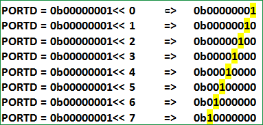
As you can see we have turned ON one LED at a time (from left to right) by keeping the rest OFF. The next ‘for loop’ for (int i=7; i>=0 && RB0==0; i--), will also do the same but this time the LED will be turned ON from right to left in a sequence, as we started from 7 and going down to 0. We have used a delay of 200ms so that we can visualize the LED being turned ON and OFF.
Now when we pass value 3 in sblink(int get) function, so the function sblink(3) will be executed which makes the value of ‘get’ as 0b00000011, hence the result on PORTD will be:
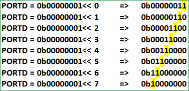
So now this time two LEDs will be turned on at any given time by using sblink(3). Similarly for sblink(7) and sblink(15), three and four LEDs will be ON in a sequence. Once this is complete we will make all the LED to be on using the line PORTD=0xFF. Check the Video below for full Demonstration.
Hope you have understood the code and thus have learnt how to use functions, ‘for’ and ‘while’ loop to get your desired outputs. Now you can tweak around the code to get your different sequence of LED blinking. Go ahead compile your code and dump it on your MCU and enjoy the output. You can use the comment section if you get stuck somewhere. I have also attached the simulation and program files here.
That's it for now in our next tutorial we will learn how to use PIC16F877A timers instead of using delay functions. You can browse all the PIC microcontroller tutorials here.
Complete Project Code
// 'C' source line config statements
// CONFIG
#pragma config FOSC = HS        // Oscillator Selection bits (HS oscillator)
#pragma config WDTE = OFF       // Watchdog Timer Enable bit (WDT disabled)
#pragma config PWRTE = OFF      // Power-up Timer Enable bit (PWRT disabled)
#pragma config BOREN = ON       // Brown-out Reset Enable bit (BOR enabled)
#pragma config LVP = OFF        // Low-Voltage (Single-Supply) In-Circuit Serial Programming Enable bit (RB3 is digital I/O, HV on MCLR must be used for programming)
#pragma config CPD = OFF        // Data EEPROM Memory Code Protection bit (Data EEPROM code protection off)
#pragma config WRT = OFF        // Flash Program Memory Write Enable bits (Write protection off; all program memory may be written to by EECON control)
#pragma config CP = OFF         // Flash Program Memory Code Protection bit (Code protection off)
// #pragma config statements should precede project file includes.
// Use project enums instead of #define for ON and OFF.
#include <xc.h>
    #define _XTAL_FREQ 20000000 //Specify the XTAL crystall FREQ
/*******Sequence blink*******/
sblink(int get) //Function definition with "get" as parameter
{
  for (int i=0; i<=7 && RB0==0; i++)
        {
       PORTD = get << i;  //LED move Left Sequence
       __delay_ms(50);
        }
          for (int i=7; i>=0 && RB0==0; i--)
        {
       PORTD = get << i;  //LED move Left Sequence
       __delay_ms(50);
        }
}

/*******MAIN Function*******/
void main() //The main function
{
TRISB0=1; //Instruct the MCU that the PORTB pin 0 is used as input for button.
TRISD = 0x00; //Instruct the MCU that all pins are output
PORTD=0x00; //Initialize all pins to 0
OPTION_REG= 0b00000000;//Enable pull up R on port B
while(1) //Get into the Infinite While loop
{

    if (RB0==0)
    {

        sblink(1); //FUNCTION CALL 1 with parameter 1
        sblink(3); //FUNCTION CALL 3 with parameter 3
        sblink(7); //FUNCTION CALL 7 with parameter 7
        sblink(15); //FUNCTION CALL 4 with parameter 15

        while(RB0==0) //If button is still pressed
        {
            PORTD=0xFF; //Turn ON all LEDs
        }
    }

}
}
Comments
Hi!
I'm trying to learn from your tutorials, and it worked until now.
I make things with 16F887 I/P and make with the appropriate setings in project, but the button sensing isn't working. I tried with another port, and with a real pull up resistor too.
Have you got any other suggestions?
Sounds odd, what do you mean by not working? Did you use a multimeter to check the voltage at the pin?
Does your simulation work fine?
i want to make a circuit to turn on all led one by one in sequence. i tried it with 4017 but in 4017 it turns off the previous led but i want previous led's remain and the led turn on in a flow . for example 1,2,3,4,5,6,7,8,9,10. can anybody help me please?
Use a multiple voltage divider circuit increase the input voltage and each LED will glow on in the sequence if you are using a MCU the method will be completely different
Hi Again,
Using MPLABX 5.20 and XC8 2.05. I believe your sblink function should be "void sblink(int get)".
Complier complains other wise?

HI, can you please help me to program PIC16F877A to light 3 leds one at a time the 4th push will put the 3 leds off using one button. I will be using 14 buttons and 42 leds. I know how to program the input and output ports and crystal osc. ect. please let me know if I can help with anything else. thank you Thys