

PIC Microcontrollers are a powerful platform provided by microchip for embedded projects, its versatile nature has made it to find ways into many applications and the phase is still going. If you have been following our PIC tutorials then you would have noticed we have already covered wide a range of tutorials on PIC microcontroller starting from the very basics. Since now, we have covered the basics we can get into more interesting stuff like the communication portal.
In the vast system of embedded applications, no microcontroller can perform all the activities by itself. At some stage of time it has to communicate to other devices to share information, there are many different types of communication protocols to share these information’s, but the most used ones are USART, IIC, SPI and CAN. Each communication protocol has its own advantage and disadvantage. Let’s focus on the IIC part for now since that is what we are going to learn in this tutorial.
What is I2C Communication Protocol?
The term IIC stands for “Inter Integrated Circuits”. It is normally denoted as I2C or I squared C or even as 2-wire interface protocol (TWI) at some places but it all means the same. I2C is a synchronous communication protocol meaning, both the devices that are sharing the information must share a common clock signal. It has only two wires to share information out of which one is used for the cock signal and the other is used for sending and receiving data.
How I2C Communication works?
I2C communication was first introduced by Phillips. As said earlier it has two wires, these two wires will be connected across two devices. Here one device is called a master and the other device is called as slave. Communication should and will always occur between two a Master and a Slave. The advantage of I2C communication is that more than one slave can be connected to a Master.
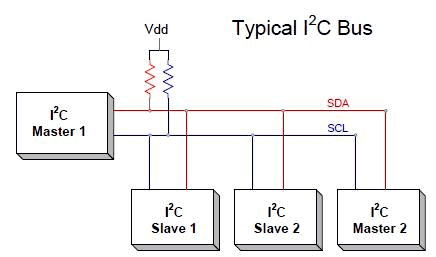
The complete communication takes place through these two wires namely, Serial Clock (SCL) and Serial Data (SDA).
Serial Clock (SCL): Shares the clock signal generated by the master with the slave
Serial Data (SDA): Sends the data to and from between the Master and slave.
At any given time only the master will be able to initiate the communication. Since there is more than one slave in the bus, the master has to refer to each slave using a different address. When addressed only the salve with that particular address will reply back with the information while the others keep quit. This way we can use the same bus to communicate with multiple devices.
Where to use I2C communication?
I2C communication is used only for short distance communication. It is certainly reliable to an extent since it has a synchronised clock pulse to make it smart. This protocol is mainly used to communicate with sensor or other devices which has to send information to a master. It is very handy when a microcontroller has to communicate with many other slave modules using a minimum of only wires. If you are looking for a long range communication you should try RS232 and if you are looking for more reliable communication you should try the SPI protocol.
I2C with PIC16F877a using XC8 Compiler
Enough of introductions, lets get into it and learn how we can use a microcontroller for performing I2C communication. Before we start make it clear that this tutorial only talks about I2C in PIC16F877a using XC8 compiler, the process will be the same for other microcontrollers but slight changes might be required. Also remember that for advanced microcontrollers like the PIC18F series the compiler itself might have some library in-built to use the I2C features, but for PIC16F877A nothing like that exists so let’s build one on our own. The library explained here will be given as a header file for download at the bottom which can be used for PIC16F877A to communicate with other I2C devices.
As always the best place to start anything is our datasheet. Look for details about I2C in datasheet and check which registers have to be configured. I am not going to explain in details since the datasheet has already done that for you. Further below I am going to explain the different functions present in the header file and their responsibility in the program.
void I2C_Initialize()
The initialize function is used to tell the microcontroller that we are going to use the I2C protocol. This can be done by setting the required bits on the SSPCON and SSPCON2 register. The first step would be to declare the IIC pins as input pins, here the pins RC3 and RC4 should be used for I2C communication so we declare them as input pins. Next we should set the SSPCON and SSPCON2 which is a MSSP control registers. We are operating the PIC in IIC master mode with a clock frequency of FOSC/(4 * (SSPADD + 1)). Refer the page numbers of the datasheet mentioned in the comment lines below to understand why that particular register is set that way.
So next we have to set the clock frequency, the clock frequency for different applications might vary, hence we get the choice from the user through the variable feq_k and use it in our formulae to set the SSPADD register.
void I2C_Initialize(const unsigned long feq_K) //Begin IIC as master
{
  TRISC3 = 1;  TRISC4 = 1;  //Set SDA and SCL pins as input pins

  SSPCON  = 0b00101000;    //pg84/234
  SSPCON2 = 0b00000000;    //pg85/234

  SSPADD = (_XTAL_FREQ/(4*feq_K*100))-1; //Setting Clock Speed pg99/234
  SSPSTAT = 0b00000000;    //pg83/234
}
Void I2C_Hold()
The next important function is the I2C_hold function which is used to hold the execution of the device until the current I2C operation is completed. We would have to check if the I2C operations have to be held before starting any new operation. This can be done by checking the register SSPSTAT and SSPCON2. The SSPSTAT contains the information about status of the I2C bus.
The program might seem to be a bit complicated since it involves a “and” and a “or” operator. When you break it as
SSPSTAT & 0b00000100
SSPCON2 & 0b00011111
It means that we are making sure that 2nd bit on SSPSTAT is zero and similarly bits from 0 to 4 are zero on SSPCON2. Then we combine all these to check the result is zero. If the result is zero the program will proceed if not it will hold there until it gets zero since it is used in a while loop.
void I2C_Hold()
{
    while (   (SSPCON2 & 0b00011111)    ||    (SSPSTAT & 0b00000100)   ) ; //check the this on registers to make sure the IIC is not in progress
}
Void I2C_Begin() and void I2C_End()
Each time while we write or read any data using the I2C bus we should begin and End the I2C connection. To begin a I2C communication we have to set the SEN bit and to end the communication we have to set the PEN status bit. Before toggling any of these bits it we should also check if the I2C bus is busy by using the function I2C_Hold as discussed above.
void I2C_Begin()
{
  I2C_Hold();  //Hold the program is I2C is busy
  SEN = 1;     //Begin IIC pg85/234
}
void I2C_End()
{
  I2C_Hold(); //Hold the program is I2C is busy
  PEN = 1;    //End IIC pg85/234
}
Void I2C_Write()
The write function is used to send any data from the master module to the salve module. This function is normally used after an I2C begin function and is followed by an I2C End function. The data that has to be written to the IIC bus is passed through the variable data. This data is then loaded into the SSPBUF buffer register to send it over the I2C bus.
Normally before writing a data an address will be written so you would have to use write function twice, once for setting the address and the other time for sending the actual data.
void I2C_Write(unsigned data)
{
  I2C_Hold(); //Hold the program is I2C is busy
  SSPBUF = data;         //pg82/234
}
unsigned short I2C_Read()
The final function that we have to know about is the I2C_Read function. This function is used to read the data that is currently on the I2C bus. It is used after asking for a slave to write some value to the bus. The value that is received will be in the SSPBUF we can transfer that value to any variable for our operation.
During an I2C communication, the slave after sending the data requested by the Master will send a another bit which is the acknowledgment bit, this bit should also be checked by the master to make sure the communication was successful. After checking the ACKDT bit for acknowledgement it should be enable by setting the ACKEN bit.
unsigned short I2C_Read(unsigned short ack)
{
  unsigned short incoming;
  I2C_Hold();
  RCEN = 1;

  I2C_Hold();
  incoming = SSPBUF;      //get the data saved in SSPBUF

  I2C_Hold();
  ACKDT = (ack)?0:1;    //check if ack bit received
  ACKEN = 1;          //pg 85/234

  return incoming;
}
That is it, these functions should be enough to set up an I2C communication and write or read data from a device. Also note that there are many other functionalities that the I2C communication can perform but for the sake of simplicity we are not discussing them here. You can always refer the datasheet to know the complete working of the
The complete code with header file for PIC16F877A I2C communication can be downloaded from the link.
Programming using the I2C header files:
Now that we have learnt how an I2C communication works and how we can use the header file created for it, let us make a simple program in which we will use the header file and write some values to the I2C lines. We will then simulate this program and check if these values are being written on the bus.
As always the program begins with setting up the Configuration bits and setting the clock frequency to 20 MHz as shown below
#pragma config FOSC = HS        // Oscillator Selection bits (HS oscillator)
#pragma config WDTE = OFF       // Watchdog Timer Enable bit (WDT disabled)
#pragma config PWRTE = ON       // Power-up Timer Enable bit (PWRT enabled)
#pragma config BOREN = ON       // Brown-out Reset Enable bit (BOR enabled)
#pragma config LVP = OFF        // Low-Voltage (Single-Supply) In-Circuit Serial Programming Enable bit (RB3 is digital I/O, HV on MCLR must be used for programming)
#pragma config CPD = OFF        // Data EEPROM Memory Code Protection bit (Data EEPROM code protection off)
#pragma config WRT = OFF        // Flash Program Memory Write Enable bits (Write protection off; all program memory may be written to by EECON control)
#pragma config CP = OFF         // Flash Program Memory Code Protection bit (Code protection off)

#define _XTAL_FREQ 20000000
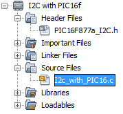
The next step would be to add the header file that we just discussed about. The header file is named as PIC16F877a_I2C.h and is could be downloaded from the link we discussed above. Make sure the header file is added in the header file of your project list, your project file structure should look like this
After making sure the header file is added to your project file include the header file in the main C file
#include <xc.h>
#include "PIC16F877a_I2C.h"
Inside the while loop we will begin the I2C communication write few random values to the I2C bus and then End the I2C communication. The random values that I have picked are D0, 88 and FF. You can input any values you want. But remember those values as we will be verifying them in our simulation.
while(1)
  {
   I2C_Begin();
   I2C_Write(0xD0);
   I2C_Write(0x88);
   I2C_Write(0xFF);
   I2C_End();
   __delay_ms(1000);
  }
The complete program can be found at the bottom of the page, you can use that or download the complete zip file of the program from here. After getting the program compile it and get ready for simulation.

Proteus Simulation:
Proteus has a nice instrument called I2C debugger which can be used to read the data on a I2C bus, so let us build a circuit using it and check if the data is being written successfully. The complete circuit diagram is shown below

Load the hex file that was generated by our program by double clicking on the Microcontroller. Then simulate the program. You will notice a window pop up that would display all the information about the I2C bus. The window for our program is shown below.
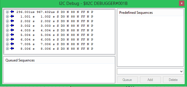
If you take a close look at the data being written you can notice that they are the same that we wrote in our program. The values are D0, 88 and FF. The values are written for every 1 sec so the time is also updating as shown below. The blue arrow indicates that it is written from master to slave it would be pointing in opposite direction if otherwise. A closer look of the data being sent is shown below.

This is just a glimpse of what I2C can do, it can also read and write data to multiple devices. We will cover more about I2C in our upcoming tutorials by interfacing various modules that work with I2C protocol.
Hope you understood the project and learnt something useful from it. If you have any doubts post them in the comment section below or use the forums for technical help.
Complete code has been given below; you can download header files with all the code from here.
Complete Project Code
/*
 * File:   IIC with PIC16F
 * Author: Aswinth Raj
 *
 * Created on 7 May, 2018, 6:42 PM
 */
#pragma config FOSC = HS        // Oscillator Selection bits (HS oscillator)
#pragma config WDTE = OFF       // Watchdog Timer Enable bit (WDT disabled)
#pragma config PWRTE = ON       // Power-up Timer Enable bit (PWRT enabled)
#pragma config BOREN = ON       // Brown-out Reset Enable bit (BOR enabled)
#pragma config LVP = OFF        // Low-Voltage (Single-Supply) In-Circuit Serial Programming Enable bit (RB3 is digital I/O, HV on MCLR must be used for programming)
#pragma config CPD = OFF        // Data EEPROM Memory Code Protection bit (Data EEPROM code protection off)
#pragma config WRT = OFF        // Flash Program Memory Write Enable bits (Write protection off; all program memory may be written to by EECON control)
#pragma config CP = OFF         // Flash Program Memory Code Protection bit (Code protection off)
#define _XTAL_FREQ 20000000
#include <xc.h>
#include "PIC16F877a_I2C.h"
int main()
{
    I2C_Initialize(100); //Initialize I2C Master with 100KHz clock
while(1)
  {
   I2C_Begin();
   I2C_Write(0xD0);
   I2C_Write(0x88);
   I2C_Write(0xFF);
   I2C_End();
   __delay_ms(1000);
}
}

Excellent articles. Please keep sending such tutorials.