
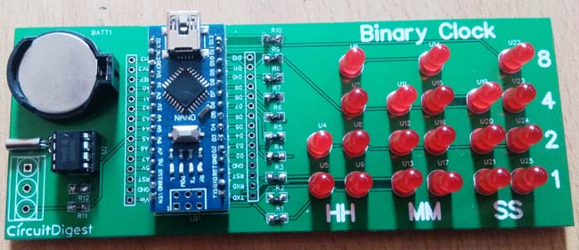
In this project, we are going to make a LED Binary Clock Using Arduino. Here we have designed a printed circuit board (PCB) to implement this clock. To design PCB layout, we have used EasyEDA online PCB designing tool.
Components Required:
- Arduino Nano
- DS1307 RTC
- 32.768Khz Crystal
- 3v coin cell
- Resistor 1k, 10k
- Power Supply
- LEDs
Circuit Diagram and Explanation:

This is very simple, cheap and interesting project for the learner. In this LED Binary Clock Circuit, we have used Arduino Nano to control the whole project like reading time from RTC and showing that on LEDs. A 3.0v coin cell is connected to RTC IC for backup. Learn more about using DS1307 RTC with Arduino here.
20 LEDs are connected here in matrix form. So here we have 6 columns and 4 rows. 2 columns used for showing hour, next two columns for minutes and next to columns for seconds. We have used 6 PNP transistor to triggers LEDs in 6 columns. The user can power the whole circuit by 5v only, here we have used laptop USB for power supply. Rest of connections are shown in circuit diagram.
Further, check the complete Arduino Code and Demonstration Video at the end of this Article.
How to Calculate and Read Time in Binary Clock:
As we are familiar with binary numbers that are zero and one. So by using these, we can show time and we can convert that binary time into the decimal. By using the number 8 4 2 1 (written on the Right side of PCB), we can convert binary to decimal.
Suppose we have a binary number like:
1 0 1 0 so it will be 10 in decimal. When we convert binary to decimal we only add ones.
Here from MSB (Most significant bit) side, we have 1 it means 8 and next is 0 means that is 0 and not to be included. Next is again 1 means 2 and the last is 0 so the last one will also not be included.
So finally we have
8+0+2+0=10
Basically, we can take it like this:
8x1 + 4x0 + 2x1 + 1x0 = 10
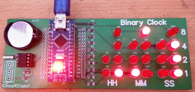
Now we can understand time from the picture:
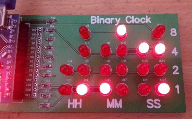
In above, we can see there are 6 columns and 4 row. In these, we have 2 columns group HH for Hour, MM for Minute and SS for seconds. At the right side of PCB, we can see row numbers 1, 2, 4, and 8, these numbers are used for converting binary number to decimal
Note we are reading columns from Right-Hand side. So first of all, see HH columns, there are two columns of time. In the first column of time, there is no led is glowing means:
2x0 + 1x0 = 0
In next column, we can see there is single led is glowing in the 1-row means. So according to 8 4 2 1
8x0 + 4x0 + 2x0 + 1x1 = 1
So in Hour HH column, we got 01.
In the first column of MM (minutes), we can see there is single led is glowing in the 1-row means
4  2  1
4x0 + 2x0 + 1x1 = 1
In the second column of MM, we can see there is single led is glowing in the row number 8 means
8  4  2  1
8x1 + 4x0 + 2x0 + 1x0 =8
So we got minute as 18
In the first column of SS (seconds), we can see there is single led is glowing in the row number 4 means
4  2  1
4x1 + 2x0 + 1x0 = 4
In the second column of SS, we can see there is two led is glowing in the row number 1 and row number 4 means
8  4  2  1
8x0 + 4x1 + 2x0 + 1x1 =5
So we got minute as 45
So finally we have got time as 01:18:45
HH     MM     SS
01     18     45
Complete Arduino Code and Demonstration Video is given at the end of this Article.
Circuit and PCB Design using EasyEDA:
To design this LED Binary Clock Circuit, we have chosen the online EDA tool called EasyEDA. I have previously used EasyEDA many times and found it very convenient to use since it has a good collection of footprints and its open-source. Check here our all the PCB projects. After designing the PCB, we can order the PCB samples by their low cost PCB fabrication services. They also offer component sourcing service where they have a large stock of electronic components and users can order their required components along with the PCB order.
While designing your circuits and PCBs, you can also make your circuit and PCB designs public so that other users can copy or edit them and can take benefit from there, we have also made our whole Circuit and PCB layouts public for this Arduino Binary Clock, check the below link:
https://easyeda.com/circuitdigest/BinaryClock-4a25419d21cc424c9989a8f6a4633f5e
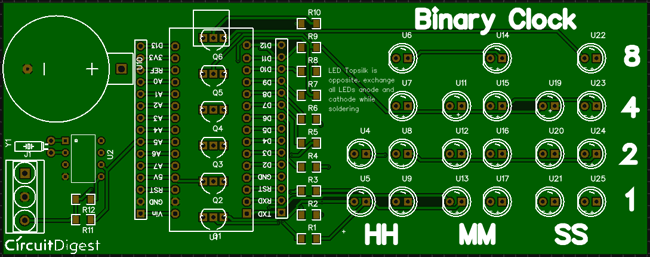
You can view any Layer (Top, Bottom, Topsilk, bottomsilk etc) of the PCB by selecting the layer form the ‘Layers’ Window.
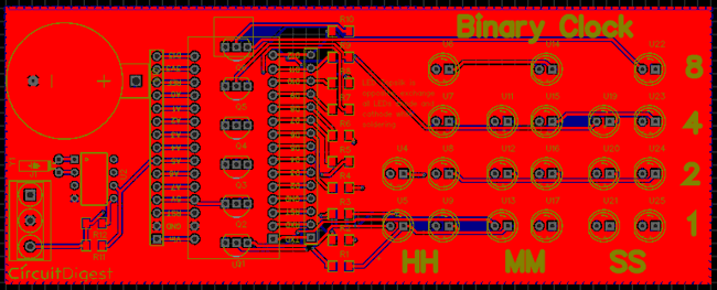
You can also view the PCB, how it will look after fabrication using the Photo View button in EasyEDA:

Calculating and Ordering Samples online:
After completing the design of this Arduino Binary Clock PCB, you can order the PCB through JLCPCB.com. To order the PCB from JLCPCB, you need Gerber File. To download Gerber files of your PCB just click the Fabrication Output button in EasyEDA editor page, then download from the EasyEDA PCB order page.
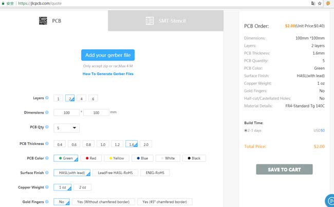
Now go to JLCPCB.com and click on Quote Now or Buy Now button, then you can select the number of PCBs you want to order, how many copper layers you need, the PCB thickness, copper weight, and even the PCB color, like the snapshot shown below:

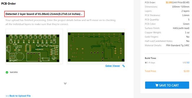
After you have selected all of the options, click “Save to Cart” and then you will be taken to the page where you can upload your Gerber File which we have downloaded from EasyEDA. Upload your Gerber file and click “Save to Cart”. And finally click on Checkout Securely to complete your order, then you will get your PCBs a few days later. They are fabricating the PCB at very low rate which is $2. Their build time is also very less which is 48 hours with DHL delivery of 3-5 days, basically you will get your PCBs within a week of ordering.
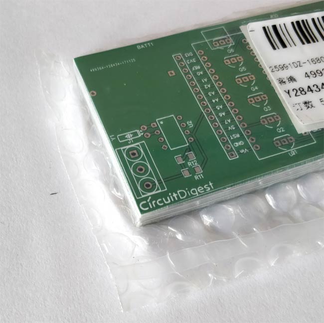
After few days of ordering PCB’s I got the PCB samples in nice packaging as shown in below pictures.

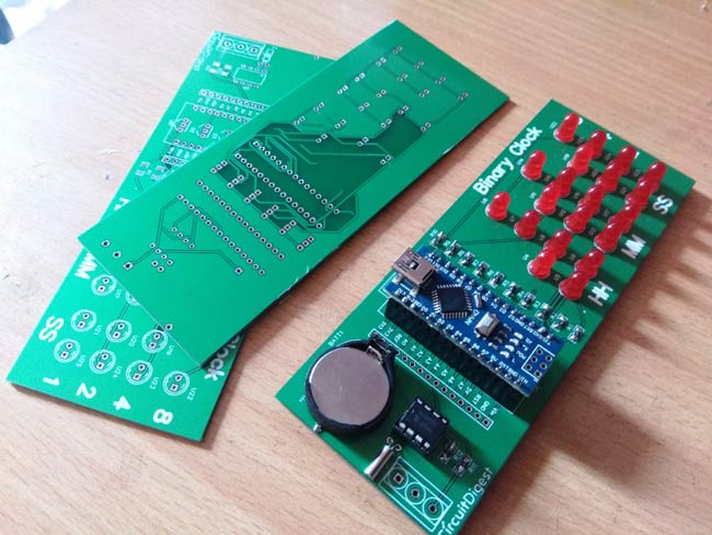
And after getting these pieces I have soldered all the required components over the PCB, placed the coded Arduino Nano and powered it with 5v supply to see the Binary Clock in Action.
Complete Project Code
#include <Wire.h>

#include "RTClib.h"

#include <TimerOne.h>
RTC_DS1307 RTC;

int temp,inc,hours1,minut,add=11;
#define d1 12

#define d2 11

#define d3 10

#define d4 9

#define d5 8

#define d6 7
#define r1 6

#define r2 5

#define r3 4

#define r4 3
int HOUR,MINUT,SECOND;
volatile int count=0;
void Clear(int d)

{

    digitalWrite(d1, HIGH);

    digitalWrite(d2, HIGH);

    digitalWrite(d3, HIGH);

    digitalWrite(d4, HIGH);

    digitalWrite(d5, HIGH);

    digitalWrite(d6, HIGH);

}
void callback()

{

  digitalWrite(13, digitalRead(13) ^ 1);

  count++;

  if(count>=7)

  count=1;

  switch(count%7)

  {

    case 1:

    Clear(d1);

    temp=SECOND%10;

    show(temp);

    digitalWrite(d1, LOW);

    break;
    case 2:

    Clear(d2);

    temp=SECOND/10;

    show(temp);

    digitalWrite(d2, LOW);

    for(int i=0;i<10000;i++)

    {

    }

    break;


    case 3:

    Clear(d3);

    temp=MINUT%10;

    show(temp);

    digitalWrite(d3, LOW);

    for(int i=0;i<10000;i++)

    {

    }

    break;
    case 4:

    Clear(d4);

    temp=MINUT/10;

    show(temp);

    digitalWrite(d4, LOW);

    for(int i=0;i<10000;i++)

    {

    }

    break;
    case 5:

    Clear(d5);

    temp=HOUR%10;

    show(temp);

    digitalWrite(d5, LOW);

    for(int i=0;i<10000;i++)

    {

    }

    break;
    case 6:

    Clear(d6);

    temp=HOUR/10;

    show(temp);

    digitalWrite(d6, LOW);

    for(int i=0;i<10000;i++)

    {

    }

    break;

  }

}
void show(int d)

{

    for(int i=0;i<1;i++)

    {

      digitalWrite(r4, !((temp>>0)&1));

      digitalWrite(r3, !((temp>>1)&1));

      digitalWrite(r2, !((temp>>2)&1));

      digitalWrite(r1, !((temp>>3)&1));

     // delay(1);

     for(int i=0;i<1000;i++);

    }

}


void setup()

{

 Wire.begin();

 Serial.begin(9600);

 RTC.begin();

 digitalWrite(next, HIGH);

 digitalWrite(set_mad, HIGH);

 digitalWrite(INC, HIGH);

 pinMode(14, OUTPUT);

 for(int i=2;i<=12;i++)

 {

  pinMode(i, OUTPUT);

  digitalWrite(i, HIGH);

 }


 if(!RTC.isrunning())

 {

 RTC.adjust(DateTime(__DATE__,__TIME__));

 }
 Timer1.initialize(1000);

 Timer1.attachInterrupt(callback);

}


void loop()

{

 int temp=0,val=1,temp4;

 DateTime now = RTC.now();

 HOUR=now.hour();

 MINUT=now.minute();

 SECOND=now.second();
 Serial.print(HOUR);

 Serial.print(":");

 Serial.print(MINUT);

 Serial.print(":");

 Serial.println(SECOND);

 delay(200);

}
Comments
Showing error during compilation, which version of Arduino will work
How to resolve this error, appearing during compilation
" Arduino: 1.8.6 Hourly Build 2018/01/03 03:33 (Windows 7), Board: "Arduino/Genuino Uno"
binclk3:107: error: 'next' was not declared in this scope
digitalWrite(next, HIGH);
^
binclk3:108: error: 'set_mad' was not declared in this scope
digitalWrite(set_mad, HIGH);
^
binclk3:109: error: 'INC' was not declared in this scope
digitalWrite(INC, HIGH);
^
Multiple libraries were found for "Wire.h"
Used: E:\AmetureElectronics\SOFTWARE\arduino-nightly-windows (1)\arduino-nightly\hardware\arduino\avr\libraries\Wire
Not used: C:\Users\Administrator\Documents\Arduino\libraries\Wire-master
Not used: C:\Users\Administrator\Documents\Arduino\libraries\Wire
Multiple libraries were found for "RTClib.h"
Used: C:\Users\Administrator\Documents\Arduino\libraries\RTClib
Not used: C:\Users\Administrator\Documents\Arduino\libraries\RTClib-master
Not used: C:\Users\Administrator\Documents\Arduino\libraries\RTClib-1.2.0
exit status 1
'next' was not declared in this scope
This report would have more information with
"Show verbose output during compilation"
option enabled in File -> Preferences.
"
I think you made some changes in the program or accidently copied only half of the program, Check you program again...
binclk3:107: error: 'next' was not declared in this scope
digitalWrite(next, HIGH);
^
binclk3:108: error: 'set_mad' was not declared in this scope
digitalWrite(set_mad, HIGH);
^
binclk3:109: error: 'INC' was not declared in this scope
The variables set_cam INC and next have not be declared according to the error
i also have same error
"next" , "set_mad" and "INC" not defined in existing programme, how and where to define for errorless compilation and proper working of the binary clock
This is because you did not install all the required libraries, follow the tutorial to install the required librarey
(1) Wire.h, (2) RTClib.h (3)TimerOne.h ... already installed these three libraries.. still gets the error mentioned in my previous mail, but what are the other libraries to be installed to get error less compilation, do you able to compile the code successfully.
These variables (next, set_mad, INC) are not used. Just comment (//) out the offending lines.
This is a great project but you could much improve your code by commenting it explaining what each section does and what variables are declared and why.
This is a pretty nice Project and I want to rebuild it. Unfortunately I can't find which resistor (1k or 10k) to use in which position.
Looking forward to an explanation.
Jan
Your circuit diagram shows 6 transistors (Q1-6, BC557A) and 10 resistors (R1-R10). These parts are not in your component list. Are 2N5087 transistors equivalent? What are the values for R1-R10? I ordered the boards to use in a computer science class that I teach and want to make sure I have the right components. Thank you for your help.
BC557A is a PNP transistor of general purpose, like a 2N5087, then should it work without problem. R1 to R10 are to limit the current over the LED's, Arduino's out pin deliver 5V, if you use red LED's (2V), my friend Georg Simon Ohm would say: R=V/I=(5V-2V)/0.02mA = 150 Ohms, in general, 150 Ohms seems to be a safe value for any conventional led. Regards and good luck.
CAN YOU PLEASE EXPLAIN THE LOGIC YOU HAVE USED TO PATTERN THE LED'S?
PLEASE REPLY....
explain what logic have you used while displaying through LED's?
PCB design - it looks like a joke, there are no wires, everything is flooded with a solid polygon)))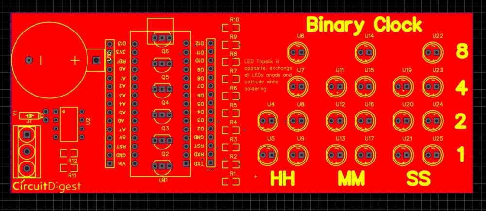
You can see this layer digram in below link
https://easyeda.com/circuitdigest/BinaryClock-4a25419d21cc424c9989a8f6a4633f5e

wonderful innovative work than you for sharing,
but how to set the time when there will be need to set the time