
In this project, we are going to develop a PIR sensor and GSM based home security system. This project is developed using 8051 microcontroller. It can be used to detect any intrusion in houses and offices and send the alerts on cell phones. Let us know how to develop this system, step by step.
Required Components
- 8051
- GSM Module
- PIR Sensor Module
- LM7805
- Bread Board
- LED
- 1K resistor
- 10K resistor
- 1000uf capacitor
- 10uf capacitor
- 10K
- Crystal 11.0592 MHz
- Power Supply
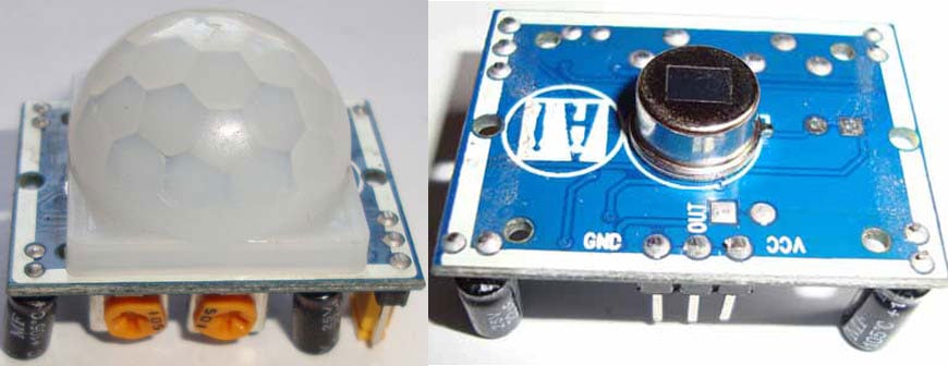
PIR Sensor
PIR sensors are used to detect living being movement. PIR is a Passive Infrared sensor, which detect infrared rays. All living being with a temperature above absolute zero emits heat energy in the form of radiation. These radiation are infrared ray. Human eye cannot see these rays because these rays are radiated at infrared wavelength. When any living being comes in range of PIR sensor, it detects heat of that living being and generate an output. PIR sensor module does not send any rays for detection, its only detects heat (Infrared). You can know more about PIR sensor in PIR sensor circuit.
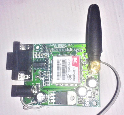
GSM Module
The SIM900 is a complete Quad-band GSM/GPRS Module which delivers GSM/GPRS 850/900/1800/1900MHz performance for voice, SMS and Data with low power consumption.
AT Commands
AT commands are used to control GSM module. There are commands for calling and messaging that we have used in this project for sending message. After receiving AT Command GSM Module respond with OK which means GSM module is working fine. Here are some useful commands
ATE0 - For echo off
AT+CMNI=2,2,0,0,0 <ENTER> - Auto opened message Receiving. (No need to open message)
ATD<Mobile Number>; <ENTER> - making a call (ATD+919610126059;\r\n)
AT+CMGF=1 <ENTER> - Selecting Text mode
AT+CMGS=”Mobile Number” <ENTER> - Assigning recipient’s mobile number
>> Now we can write our message
>> After writing message
Ctrl+Z - send message command (26 in decimal).
ENTER=0x0d in HEX
Working
In this project we have used 8051 microcontroller for controlling the whole process of the project. A PIR sensor is used for sensing human presence. And when PIR sensor sense any movement in targeted area of room then it gives a HIGH logic to microcontroller and then Microcontroller take place and make a call via GSM module using AT commands. Controller calls to a predefined mobile number and at the same time it also sends a message to the same number via GSM Module.

Circuit Diagram

Circuit connections are shown in the above circuit diagram. GSM module’s Rx and Tx pins are directly connected to Tx and Rx pin of microcontroller And supply by using a 12 Volt adaptor. A PIR Sensor module’s Dout pin is directly connected at pin 21 (P2^0) of Microcontroller with a 10K pull up resistor. A 11.0592 MHz Crystal oscillator is used in this circuit for generating clock signal for microcontroller. And a 5 volt voltage regulator is used for provide 5 volt for the whole circuit.
Program Explanation
In programming, first of all we include header file and defines input and output pin and variables.
#include<reg51.h>
sbit PIR=P2^0;
After this we have created a function for delay.
 void delay(int itime)
{
    int i,j;
    for(i=0;i<itime;i++)
    for(j=0;j<1275;j++);
}
Here we have some function that we have used in our program. In this we have configure 9600bps baud rate at 11.0592MHz Crystal Frequency, and function for receiving. We are monitoring the SBUF register for receiving data.
void Serialbegin()
{
 TMOD=0x20;
 SCON=0x50;
 TH1=0xfd;
 TR1=1;
}
void Serialwrite(char dat)
{
  SBUF=dat;
  while(!TI);
  TI=0;
}
void Serialprintln(char *p)
{
  while(*p)
  {
    Serialwrite(*p);
    p++;
  }
  Serialwrite(0x0d);
}
After this in main program we have initialized UART and then we read the output of PIR sensor module. And if sensor gives HIGH logic to controller then microcontroller make a call with sending a message at the same time by using AT commands.
void main()
{
    //P2=0x00;
    Serialbegin();
    Serialprintln("ATE0");
    delay(50);
    while(1)
    {
      if(PIR)
      {
        Serialprintln("ATD+919821757249;");
        delay(1000);
      //  lcdcmd(192);
      //  lcdprint("Message Sending.");
        Serialprintln("AT+CMGF=1");
        delay(50);
        Serialprintln("AT+CMGS=\"+919821757249\"");
        delay(50);
        Serialprintln("Someone is Enter in your Place.");
        delay(50);
        Serialwrite(26);
      }
    }
}
Complete Project Code
#include<reg51.h>
sbit PIR=P2^0;
 void delay(int itime)
{
    int i,j;
    for(i=0;i<itime;i++)
    for(j=0;j<1275;j++);
}
void Serialbegin()
{
 TMOD=0x20;
 SCON=0x50;
 TH1=0xfd;
 TR1=1;
}
void Serialwrite(char dat)
{
  SBUF=dat;
  while(!TI);
  TI=0;
}
void Serialprintln(char *p)
{
  while(*p)
  {
    Serialwrite(*p);
    p++;
  }
  Serialwrite(0x0d);
}
void main()
{
    //P2=0x00;
    Serialbegin();
    Serialprintln("ATE0");
    delay(50);
    while(1)
    {
      if(PIR)
      {
        Serialprintln("ATD+919821757249;");
        delay(1000);
    //    lcdcmd(192);
   //     lcdprint("Message Sending.");
        Serialprintln("AT+CMGF=1");
        delay(50);
        Serialprintln("AT+CMGS=\"+919821757249\"");
        delay(50);
        Serialprintln("Someone is Enter in your Place.");
        delay(50);
        Serialwrite(26);
      }
    }
}
Comments
i am planning to do this as my project...will it work out if i follow all the instructions here ...? and also i have only 1 mnth time,is it enough??
Yes you can make it. it will work fine.
and you time period is good enough for completing this project.
best of luck
Can i use more than one sensor in this project?what changes will have to be done if i use more than one sensor?
#include<reg51.h>
sbit PIR=P2^0;
sbit PIR1=P2^1;
void delay(int itime)
{
int i,j;
for(i=0;i<itime;i++)
for(j=0;j<1275;j++);
}
void Serialbegin()
{
TMOD=0x20;
SCON=0x50;
TH1=0xfd;
TR1=1;
}
void Serialwrite(char dat)
{
SBUF=dat;
while(!TI);
TI=0;
}
void Serialprintln(char *p)
{
while(*p)
{
Serialwrite(*p);
p++;
}
Serialwrite(0x0d);
}
void main()
{
//P2=0x00;
Serialbegin();
Serialprintln("ATE0");
delay(50);
while(1)
{
if(PIR)
{
Serialprintln("ATD+919821757249;");
delay(1000);
lcdcmd(192);
lcdprint("Message Sending.");
Serialprintln("AT+CMGF=1");
delay(50);
Serialprintln("AT+CMGS=\"+919821757249\"");
delay(50);
Serialprintln("Someone is Enter in your Place.");
delay(50);
Serialwrite(26);
}
if(PIR1)
{
Serialprintln("ATD+919821757249;");
delay(1000);
lcdcmd(192);
lcdprint("Message Sending.");
Serialprintln("AT+CMGF=1");
delay(50);
Serialprintln("AT+CMGS=\"+919821757249\"");
delay(50);
Serialprintln("Someone is Enter in your Place.");
delay(50);
Serialwrite(26);
}
}
you can use this code for two sensor..
how to use code in 8051 and i used one and multiple sensor so, pls give me full information
here is what i got why building the code on mikroc
0 1 mikroc8051.exe -MSF -DBG -pAT89C51 -ES -DL -O11111114 -fo8 -N"C:\Users\Enoch\Documents\Mikroelektronika\Security system with PIR\Security System PIR.mcp51" -SP"C:\Users\Public\Documents\Mikroelektronika\mikroC PRO for 8051\defs\" -SP"C:\Users\Public\Documents\Mikroelektronika\mikroC PRO for 8051\Uses\ATMEL\" -SP"C:\Users\Enoch\Documents\Mikroelektronika\Security system with PIR\" "Security System PIR.c" "__Lib_Math.mcl" "__Lib_MathDouble.mcl" "__Lib_System.mcl" "__Lib_Delays.mcl" "__Lib_UART_Timer1.mcl" "__Lib_CType.mcl" "__Lib_CString.mcl" "__Lib_CStdlib.mcl" "__Lib_CMath.mcl" "__Lib_Conversions.mcl" "__Lib_Sprintf.mcl" "__Lib_PrintOut.mcl" "__Lib_Sprinti.mcl" "__Lib_Sprintl.mcl" "__Lib_Time.mcl" "__Lib_Trigonometry.mcl" "__Lib_Button.mcl" "__Lib_Keypad4x4.mcl" "__Lib_Manchester.mcl" "__Lib_OneWire.mcl" "__Lib_PS2.mcl" "__Lib_Sound.mcl" "__Lib_SoftI2C.mcl" "__Lib_SoftSPI.mcl" "__Lib_SoftUART.mcl" "__Lib_GlcdFonts.mcl" "__Lib_Glcd.mcl" "__Lib_LcdConsts.mcl" "__Lib_Lcd.mcl" "__Lib_RS485.mcl" "__Lib_T6963C.mcl"
0 122 Compilation Started Security System PIR.c
1 325 Too many initializers Security System PIR.c
14 318 Assigning to non-lvalue 'TR1' Security System PIR.c
20 318 Assigning to non-lvalue 'TI' Security System PIR.c
43 324 Undeclared identifier 'lcdcmd' in expression Security System PIR.c
44 324 Undeclared identifier 'lcdprint' in expression Security System PIR.c
57 324 Undeclared identifier 'lcdcmd' in expression Security System PIR.c
58 324 Undeclared identifier 'lcdprint' in expression Security System PIR.c
68 315 Invalid expression Security System PIR.c
67 402 ; expected, but '' found Security System PIR.c
68 424 '}' expected '' found Security System PIR.c
0 102 Finished (with errors): 24 Sep 2016, 12:23:25 Security System PIR.mcp51
saddam your code giving error in this line #include<reg51.h> how can i right it?
please,can i get code by using 8051? thank you.
if you wont to use ATMEG328 how can be use
sir, I am going to do a project almost the same as this one. I want to do the simulation in Proteus please send me the full proteus circuit diagram and the code by my email address.
best project!
Hello sir, can i remove the GSM module instead attach a fan with turns on & off on human detection.
kindly provide the code changes requirment for this.Thank you.
how to programme the 8051 microcontroller
what device to use pls tell soon.sir
i want do some project
Check this one: Getting Started with 8051 Microcontroller
Sir,
I want to make a security system that's have 2 pir motion sensor, one alarm , and its send massage and call to three mobile numbers. Kindly upload source code for this project.
Which compiler to be used to generate hex code.
Can you please provide the complete C program to compile and burn
Keil compiler is used to generate the Hex code. Check our 8051 section.
sir,
when i tried to cover the c code to hex code on keil v5
error
line (43): warning C206: ''lcdcmd' : missing function-prototype
line (43): error C267: 'lcdcmd' : requires ansi-style prototype
target not created
this is the error show , how to correct this error
Hi,
I need little help on coding as the current one is giving a little problem.
When there is movement the PIR gives output which makes microcontroller sends signal to GSM module to send SMS.
Problem : it continously send SMS when there is continous movement after some delay!!!!
I would like the coding to send sms when there is first time movement and then it should stop sending sms even when there is continous High signal from PIR. It should again send SMS when PIR stops and then again send high signal.
Hope I have been clear on the above!!!. Waiting for the results from great programmer here.
I made the circuit according to the circuit diagram and I just checked and found that even without PIR the Microcontroller is sending SMS throgh GSM???? I followed as per circuit diagram. Any thing to addup which I missed???
Further please check my other request where I need coding to send SMS only at input trigger.
Waiting...
Deepak
Hi Deepak,
You need to understand about the PIR sensor, please check this article about PIR sensor. First you need to reduce the sensitivity of PIR by using the Distance control knob and then you need to configure PIR in Non Repeatable Triggering Mode and set some time Time delay in PIR using Time Delay knob, to prevent sending repeated SMS. Also set some delay in 8051 Coding.
yes sir i chechked the article of pir and done according to that no sollution
a major problem is that when i am removing the pir sensor from the circuit still the microcontroller is sending high op to gsm and sms is comming to my no where is the error ?is there anything in coading is wrong ?
Sir,
I want C programming of pir and GSM based home security system using AVR(atmega16).
Thank you
The microcontroller in your instructible is quite different from the one in the circuit diagram. Why is that so??????....… why talk about 8051 and then you use AT8......?????
sir i dont have time sir plz say me that how the AT COMMANDS are used and how can i dump in to module plz help me
i ca't verify this code #include<reg51.h>.
what shoul i do??
can you give me link 8051 library to add in arduino library??
Which Software can i simulate this code ?
You can use Proteus to simulate the code, you may also need to install GSM library in Proteus for GSM module.
how to use (install) code in 8051 pls information in details i used 1,2,3 sensor so, how to use code for 1 sensor to multiple sensor
Check this article to: Getting Started with 8051 Microcontroller
HOW I CAN GET THE BURNER? ARE U SOLD THE BURNER? CAN I BUY WITH YOU?
fathi.c(43): error C267: 'lcdcmd': requires ANSI-style prototype...
i got this message..how i want to solve this problem? what code must added?
This is a very nice demonstration , congratulations on that part .
I am doing a college project that requires me to do the same thing as you have done but using mspp430 mc instead of 8051 . so can you please send me any instruction/changes/modification regarding the same ?
My email id is - [] , you can contact me there . Thanks in advance.
Sir,
you have written the LCD function calls in the main program without including the LCD header file. If I want to compile the program, do I get any errors corresponding to the LCD instructions. My doubt is "you didn't used the LCD in the project, even though you have written the LCD functions in the code". What is the necessary ? If you don't mind can you justify my doubt please...
Thank you sir .!
if i use at89s52 in place of at89c51 is there is any change in the code
because at89c51 is not available in the market so please help me out from these problem thnks
As PIR sensor is used to detect motion of living beings .but how can we distinguish between the motion of human being and other living beings....
Cool!!
Excuse me but if I want to check in MSP-EXP430F5529LP, will the code be changed?and how
sir i am not able to load the hex code using flash magic please provide the schematic diagram to load it or what programmer should i use please tell me
Check here to learn How to upload the code in 8051: Getting Started with 8051 Microcontroller
after loading the hex in the microcontroller succesfully the error that is occuring on my project is that the sensing the human interface single time but sending sms repetadely several times what is error behind these please help me out
Learn more about using PIR sensor here: PIR Sensor Based Motion Detector, you should trigger it only once
sir, I am going to do a project almost the same as this one. I want to do the simulation in Proteus please send me the full proteus circuit diagram and the code by my email address
sir, in a code which you have mentioned , which number dose i change in coding , whether it is which i use in GSM module or which i use in mobile phone.......plz kidenly clear my query
Thank you
Sir, can i implement this one with home automation (already you given seperately) both of them how to implemented with single ardunio and single gsm module..? And then what would be change in program?
Sir pls i want to ,gsm based home security and applience control both,h ence control and security both in this project qhat changes can i do ?
nice project..
sir...., what is the need of crystal in the circuit??
i select this project to my assignment. so i want to know program will work ?
hi this code is working or not, i tried to execute but i didn't get the out put
can i use buzzer instead of gsm module?
this project and this program realy working
Is the code be changed if i use SIM800L GSM module? and can you provide me a tutorial to how to connect adapter to SIM800L?
hello sir, I followed this circuit diagram and code exactly same as shown at this site but still there is no output. what to do? is the given circuit diagram and code is correct?
Pls can I use mikroC to program this code and use PICKIT3 to burn the code
You can use pickit3 to upload hex file to PIC, so compile the program on mickroC and get the hex file and then use it to upload
is it possible to do these using 16f88 how can i use arduino or pic16f88 for the circuit
what if i want to use a PSoC with the PIR Sensor and GSM Module Based Home Security System?
Please help me, how to burn microcontroller ?
Please give me the assemble code, please,
Can I use GSM sim800A instead of 900A. Will there be any change in the code??
Can i use sim 800a what will be the changes plus does anybody have link of this circuit because i have tried it on proteus it isn't working i've to submit this product in a week can anyone help ?

Can I use 5v battery instead of 7805 .