Hello Guys / Gals,
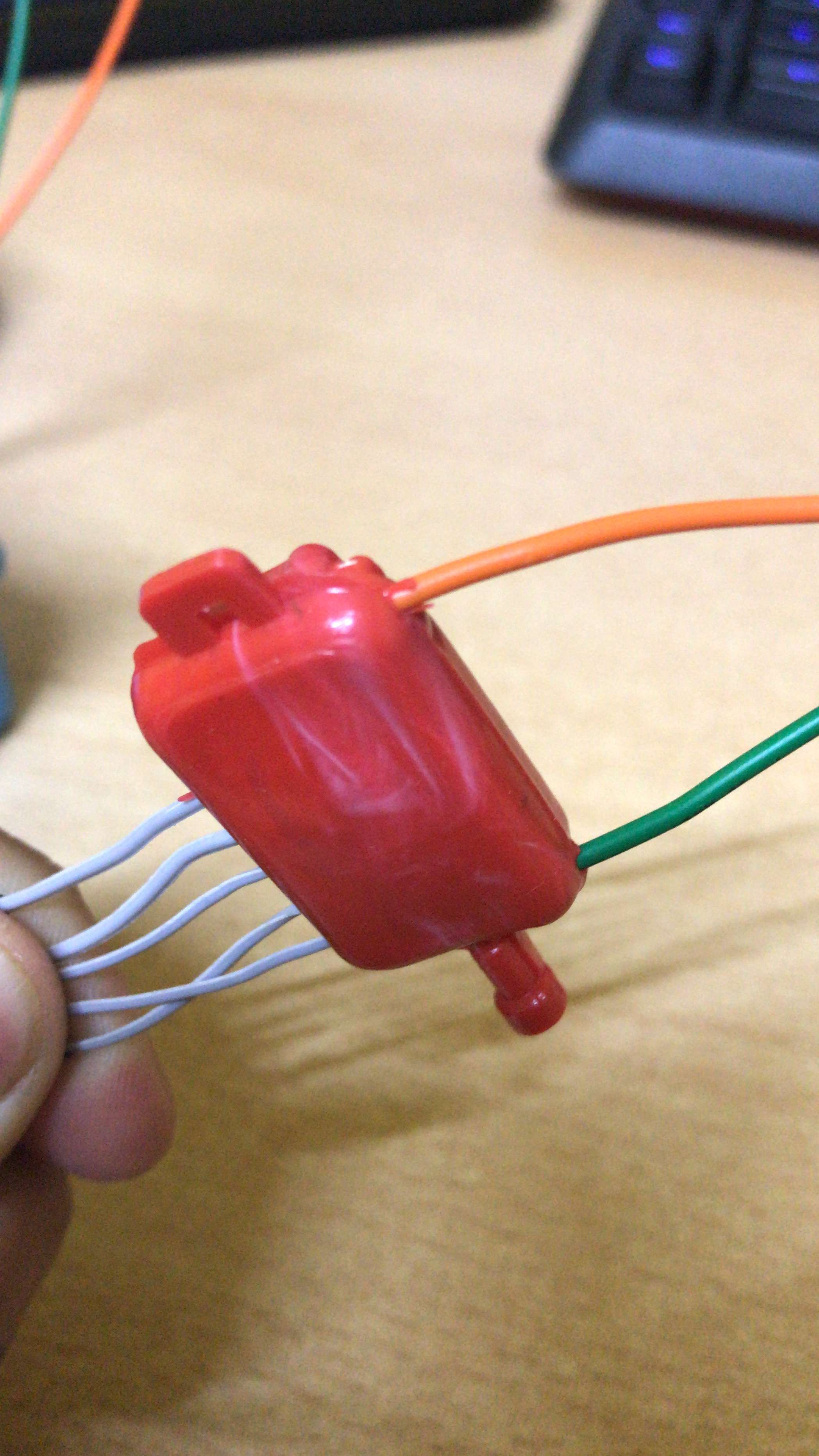
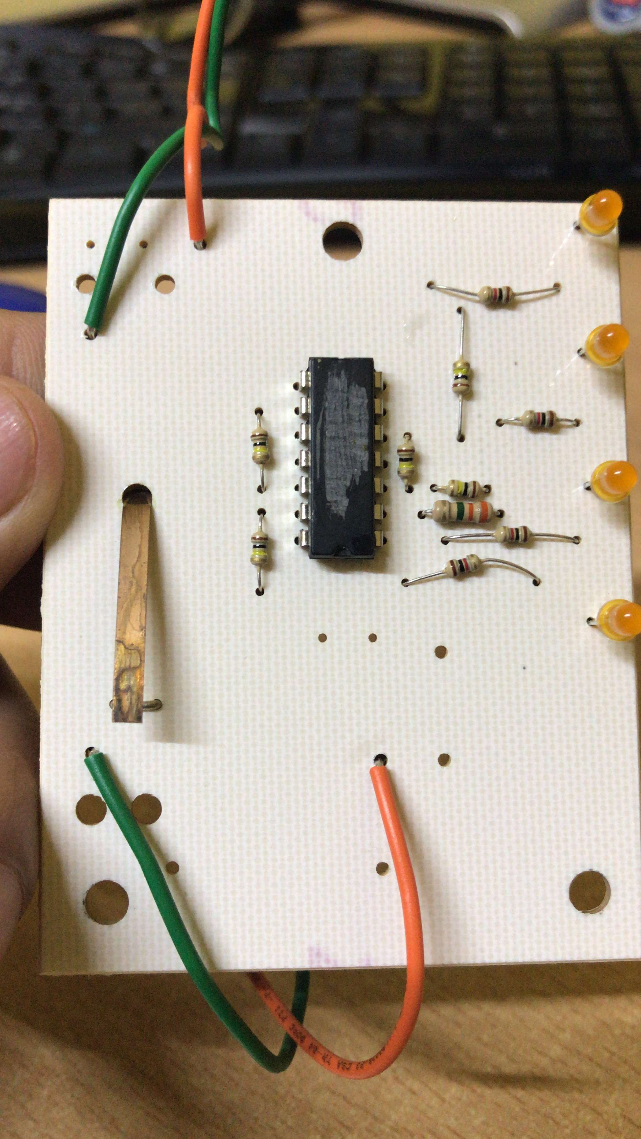
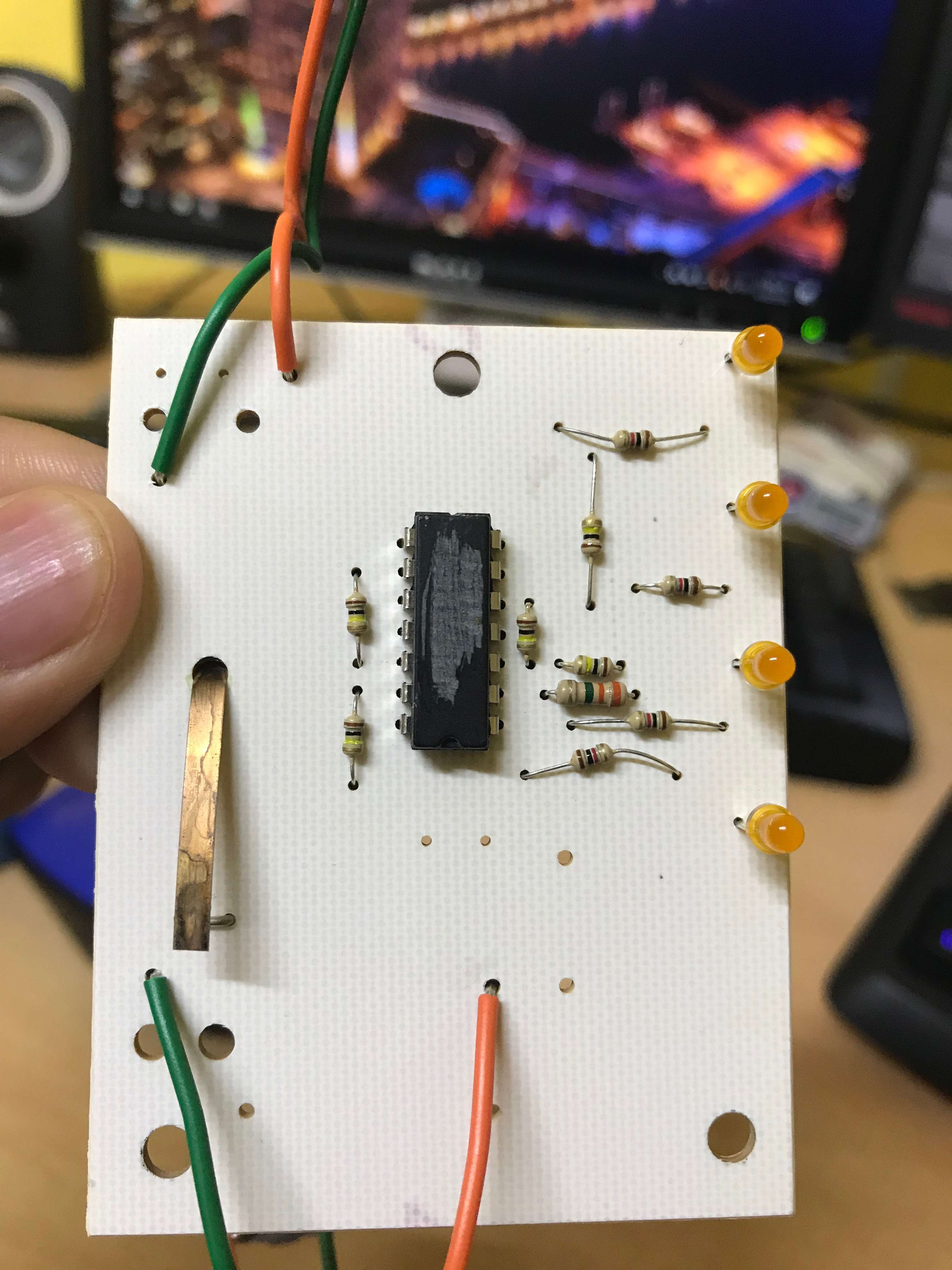
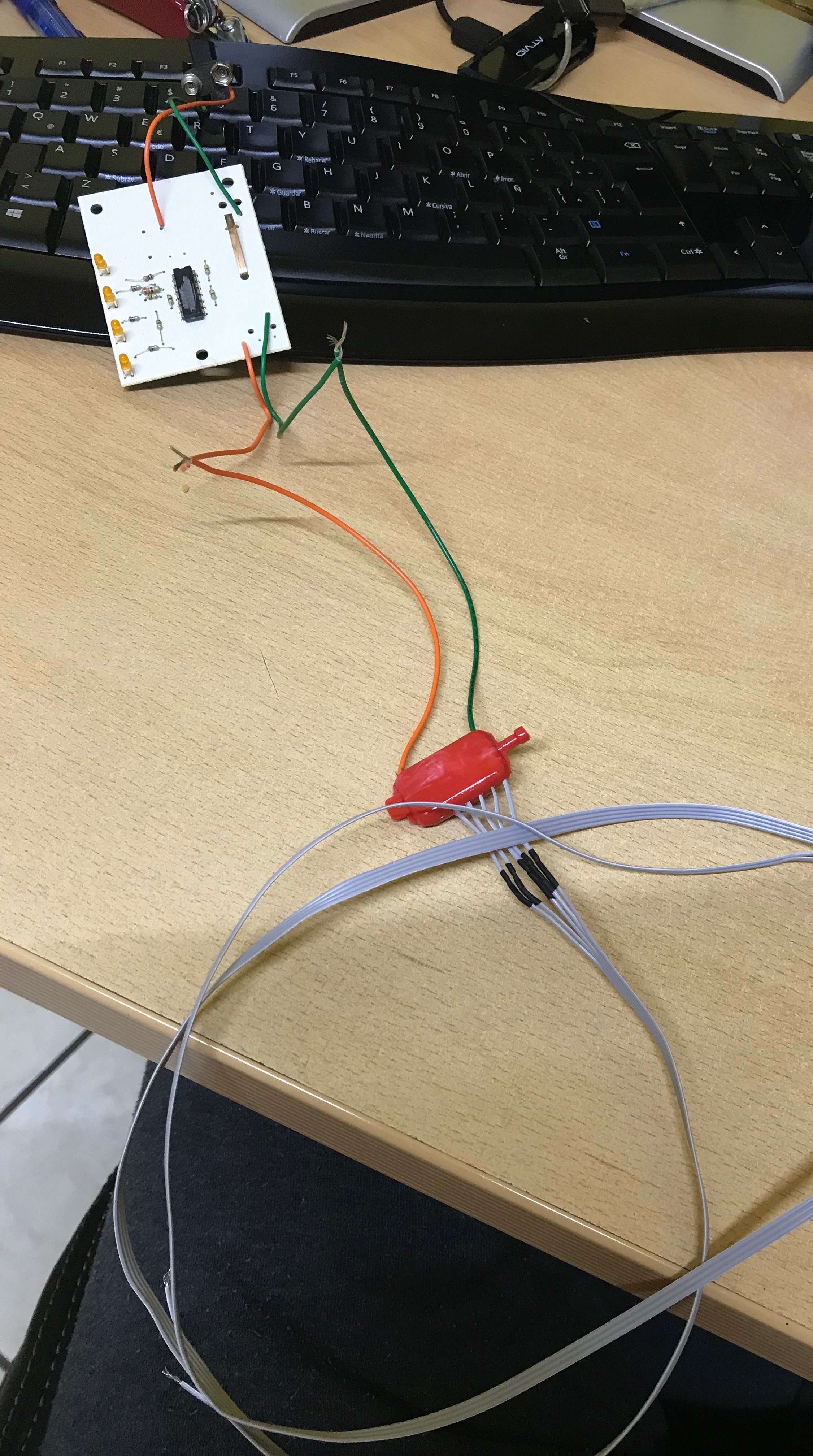
I need your help, I'm a complete noob to this, I love it, makes me so happy to build things, I have a circuit that looks really simple its a water level sensor that was given too me for school, but I want to make it better add a buzzer. Its pretty simple I think, its a 9v battery to a circuit then to the red box that has 5 wires that you place in the water tank and depending on the depth if water touches the cable a led turns on. But I want to know how to build it.. They scratched the model of chiped used and the red box you cant open it so I dont know whats in it can you smart guys and gals please help me find out what model of chip is and whats in the damn red box Im trying to peel it but dont want to break ti Maybe a explanation on how it works?
https://imageshack.com/a/img922/9629/IYxVBK.jpg
https://imageshack.com/a/img922/6060/Rh4XZ5.jpg
https://imageshack.com/a/img924/1680/DSFsm3.jpg
https://imageshack.com/a/img923/6836/fOWeEf.jpg
https://imageshack.com/a/img922/1613/3o2nnm.jpg

Hello Jerry,
I have checked out your board and it seems like a overkill circuit for a water level probe. The chip is a LM324 quad op-amp but de VCC of the chip is running through a 33 ohm resistor which is also feeding the the probe, while the inverted input of all four op-amps are attached to the 9V directly. The non-inverted inputs are joined to the VCC too via five 100K resistor in series to ground and each input is joined to these resistors. The probe seems to have a boost converter in it, which boost the voltage up depending on the probes touching the water. I have attached a link to a picture in which you can find a similar circuit, only much easier to follow and without a complex probe.
R1,R2,R3 and R5 are 100K, R4 and R6 are 10K, R7-R10 schould be 1K and the four resistors at the left bottom together with the ground pin are the probe connections. These resistors should be all the same value but you should find out the value your self by experimenting. You also wanted to add a buzzer to this circuit and here you can use a NPN transistor like the BC547, attach the base to one of the led's (of choice) anode side, the emiter to the ground (B-) pin and the buzzer between the B+ and the collector. The chip here is also the LM324, the VCC pin is 4 and the GND pin is 11. This chip has 4 op-amps in it and it is best that you search for the datasheet of this device on the internet, to find the connections to each op-amp.
Good luck!

Jerry
PermalinkForgot to add this image.:
https://imageshack.com/a/img923/876/TpU3Cw.jpg
- Log in or register to post comments
Joined February 15, 2018 1Thursday at 12:34 AM