

Building an FM Transmitter and broadcasting our own signals on the air is really a fun project to do. Especially, with this circuit since it does not require you to wound your own inductor or use a trimmer and spend hours in tuning your circuit to make it work properly. In this project you will learn How an FM Transmitter Works and how you can build your own with subtle components. We are adapting the circuit given by Tony Van Roon given in the book “Circuits for Hobbyists” (Page 75). This is an excellent book to start with if you want to do some tinkering with electronics.
Note: Generating Frequencies that could affect your FM band or any other communication band might be considered against the law in your country. Kindly use this circuit for education purpose only and make sure your signal is not too strong to disrupt any communication near you. For any mishaps neither the website nor the author can be held responsible.
Components Required:
The main theme of this Simple FM Transmitter Circuit, is to build it with minimum available components without using inductor coil and variable capacitor and yet make it work to its maximum potential. The components required to build this project is listed below
- SN74LS13 – 4 Input NAND gate Schmitt Trigger
- LM386 –Audio Amplifier
- 3.5 mm Audio Jack
- 7805 Voltage Regulator
- 1000uf, 100uf, 10uf, 0.1uf, 22pf Capacitors
- 9V Battery
- Bread board
- Connecting wires
- Speakers for testing
Working of FM transmitter:
Before we dive into the circuit and start building it, I think we should know How an FM Transmitter Works so that it would make sense while building it. If you are not interested in this theory you can skip this section and fall down into the circuit diagram.
An overview of the FM transmitter is given using the Block Diagram below
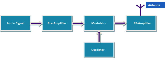
The term FM stands for “Frequency Modulation” meaning we are going to vary the frequency of an audio signal so that it gets capable of travelling a long distance over the air. Every Audio device like an IPod or music player produces audio signals in form of sine waves; these are called the modulating signal or the modulating frequency. This modulating signal has the complete information about the song or music that is being played. But these guys are week; they cannot travel a long distance and will most likely die before reaching the receiver (Radio).
So, we have to find someone who is really strong and can actually carry these week modulating signals to their receivers. These strong signals are called the Carrier signals or the carrier frequency. The technique in which we combine this strong Carrier frequency with the modulating frequency is called as Frequency modulation (FM). Here the frequency of the carrier wave is modified in accordance with the frequency of the Modulating signal.
As shown in the above block diagram the Modulating signal is produced in the Audio Signal box, then it is amplified using a pre-amplifier. The oscillator produces a strong carrier frequency to which the signal is modulated using a modulator. To further increase the range an RF-Amplifier and an antenna is used.
In our circuit, the Audio Signal is given by a phone or IPod. The Pre-Amplification is done using the LM386 Audio Amplifier IC. The 74LS138 along with 22pF capacitor acts as a Tank circuit which produces a strong carrier frequency and modulate it with our amplified audio signal. We do not have a RF-Amplifier in our circuit, but it can be added if you need to achieve a higher range.
Circuit Diagram:
The Circuit Diagram of this Simple FM Transmitter is shown in the image below.

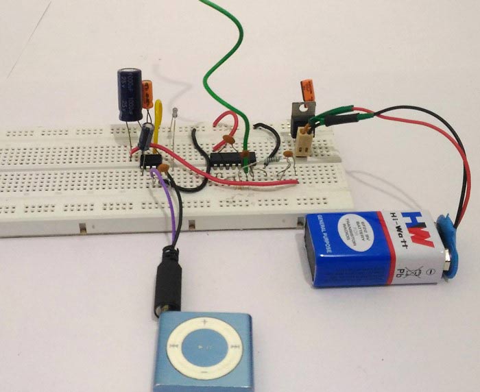
It can be built on a breadboard or soldered to a Perf board. The complete circuit can be powered using a 9V Battery. If you are using an adapter to power it make sure you add filter capacitor to reduce the noise from switching. The circuit uses an LM386 Audio amplifier which acts as an Pre-Amplifier, this IC amplified the audio signals from the audio device and feeds it to the Oscillating circuit.
The Oscillating circuit should have an Inductor and a Capacitor. In our project the IC 74LS13 which is a 4-Input NAND gate Schmitt Trigger is designed to oscillate at 3rd order Harmonics which is around 100Mhz. A filter capacitor across the power rails of the IC is very important to make it working.
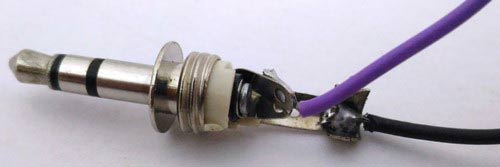
The 3.5mm Audio Jack has three terminals in which are for channel L, channel R and Ground. We short the channel pins so that it becomes mono channel as shown in picture below and connect it to pin 3 and ground is connected to pin 2 of LM386.
An 8-ohm speaker is used for testing the Amplifier circuit. This speaker should be disconnected while we are tuning the circuit.
Tuning into the right FM band:
Thanks to the approach given by Tony Van Roon tuning this FM Transmitter circuit is very easy compared to other circuits since it does not have an Inductor or a trimmer. To start with simply power on the circuit and connect the speaker to the circuit as shown in the circuit above. Now connect the IPod or any audio device to the 3.5mm jack and play the music. You should be able to hear your audio through the speaker. If not the problem should be with your LM386 connections. If the audio can be heard, disconnect the speaker and proceed with the tuning process.
Use a Radio with tuner and start turning your knob to know at which frequency you oscillator is broadcasting. The best way is to check around 100Mhz as it would most likely work around this frequency. Keep your volume at your maximum and tune slowly till you can hear the song that is being played through your audio source. You can also see the video below to know how I tuned it.
You can try the following if you hit a wall:
- If you hear a strange noise at a particular frequency and want to find to if this is your oscillator frequency. Simply turn off the circuit and turn in again, your radio should produce a crackling noise if the frequency is correct
- Extend the antenna of your radio to its full length and place it close to the circuit initially
- Change the operating voltage within 4.5 to 5 V to change the frequency at which you are broadcasting because sometimes your frequency might have clashed with another popular FM band.
- (Totally optional) If you have a variable capacitor of range 0-22pf you can replace the 22pf cap with this trimmer and try changing its values.
Once you find out at which frequency you are working you can position the antenna in the right direction and enjoy your broadcasted music. Hope you got the project working. If any quires you can reach me through the comment section below.
Comments
About error
BRO I've got the dead band it's 96.0 mhz
But it's not transmitting the audio signals
Amplifier is working
All connections are perfect
Plz help me...!
Hi Sourabh,
Hi Sourabh,
Are you sure you are in the correct Deadband? Turn off your circuit power and check if that dead band is disappearing
Electronics
Hey sir. I would like to thank you for this interesting article. I would like to create a walky talkie based on this circuit. Is this possible? If yes im happy! But if it isn't, why?
Electronics
Oh i forgot to tell that fact. The walky talky will not be FM broadband but in citizen band (27MHz). Is this possible? Thank you very much.
fm transmitter range
bro how to increase the range for 200 metrs
I dont think its easy. But
I dont think its easy. But please let me know if you have figured it out
electronics
pls sir, i want to build this Circuit as a project. can it work?
can we replace the ipod with
can we replace the ipod with a mic?
Bro am impressed with this
Bro am impressed with this work.. But I find it difficult to get the NAND gate please is there any other means pls help

I'm In Touch With It