

In this project we are going to interface LDR with ATMEGA8 microcontroller, and with this we can measure LIGHT INTENSITY in the area. In ATMEGA8, we are going to use 10bit ADC (Analog to Digital Conversion) feature to measure the light intensity.
Am LDR is a transducer which changes its resistance when LIGHT falls on its surface changes. LDR sensor is available in different sizes and shapes.
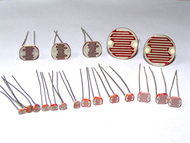
LDRs are made from semiconductor materials to enable them to have their light sensitive properties. There are many types of materials used, but one which is popular is CADMIUM SULPHIDE (CdS). These LDRs or PHOTO REISTORS work on the principle of “Photo Conductivity”. Now what this principle says is whenever light falls on the surface of the LDR (in this case) the conductance of the element increases or in other words the resistance of the LDR decreases when the light falls on the surface of the LDR. This property of the decrease in resistance for the LDR is achieved because it is a property of semiconductor material used on the surface. LDR are used most of times to detect presence of light or for measuring the intensity of light.
There are different types of LDR as shown in above figure and each have different specifications. Typically an LDR will have 1MΩ-2MΩ at total darkness, 10-20KΩ at 10 LUX, 2-5KΩ at 100 LUX. The typical resistance to LUX graph of an LDR is shown in figure.
As shown in above figure, the resistance between the two contacts of sensor decreases with light intensity or the conductance between two contacts of sensor increases.
Now for converting this change in resistance to change in voltage, we are going to use voltage divider circuit. In this resistive network we have one constant resistance and other variable resistance. As shown in figure, R1 here is a constant resistance and R2 is FORCE sensor which acts as a resistance.
The midpoint of branch is taken to measurement. When resistance R2 changes , the Vout changes with it linearly. So with this we have a voltage which changes with weight.
Now important thing to note here is, the input taken by the controller for ADC conversion is as low as 50µAmp. This loading effect of resistance based voltage divider is important as the current drawn from Vout of voltage divider increases the error percentage increases, for now we need not worry about loading effect.
What we are going to do here is we are going take two resistors and form a divider circuit so that for a 25Volts Vin, we get a 5Volt Vout. So all we have to do is multiply the Vout value with “5” in the program in order to get the real input voltage.
Components
Hardware: ATMEGA8, power supply (5v), AVR-ISP PROGRAMMER, JHD_162ALCD (16*2LCD), 100uF capacitor, 100nF capacitor (5 pieces), 10KΩ resistor, LDR (Light Dependent Resistor).
Sofware: Atmel studio 6.1, progisp or flash magic.
Circuit Diagram & Working Explanation
In circuit PORTD of ATMEGA8 is connected to data port LCD. In 16*2 LCD there are 16 pins over all if there is a back light, if there is no back light there will be 14 pins. One can power or leave the back light pins. Now in the 14 pins there are 8 data pins (7-14 or D0-D7), 2 power supply pins (1&2 or VSS&VDD or gnd&+5v), 3rd pin for contrast control (VEE-controls how thick the characters should be shown) and 3 control pins (RS&RW&E)
In the circuit, you can observe that I have only took two control pins. The contrast bit and READ/WRITE are not often used so they can be shorted to ground. This puts LCD in highest contrast and read mode. We just need to control ENABLE and RS pins to send characters and data accordingly.
The connections for LCD are given below:
PIN1 or VSS ------------------ground
PIN2 or VDD or VCC------------+5v power
PIN3 or VEE---------------ground (gives maximum contrast best for a beginner)
PIN4 or RS (Register Selection) ---------------PB0 of uC
PIN5 or RW (Read/Write) -----------------ground (puts LCD in read mode eases the communication for user)
PIN6 or E (Enable) -------------------PB1 of uC
PIN7 or D0-----------------------------PD0 of uC
PIN8 or D1-----------------------------PD1 of uC
PIN9 or D2-----------------------------PD2 of uC
PIN10 or D3-----------------------------PD3 of uC
PIN11 or D4-----------------------------PD4 of uC
PIN12 or D5-----------------------------PD5 of uC
PIN13 or D6-----------------------------PD6 of uC
PIN14 or D7-----------------------------PD7 of uC
In the circuit you can see that we have used 8bit communication (D0-D7) however this is not a compulsory, we can use 4bit communication (D4-D7) but with 4 bit communication program becomes a bit complex. So from mere observation from above table we are connecting 10 pins of LCD to controller in which 8 pins are data pins and 2 pins for control.

The voltage across R2 is not completely linear; it will be a noisy one. To filter out the noise capacitors are placed across each resistor in the divider circuit as shown in figure.
In ATMEGA8, we can give Analog input to any of FOUR channels of PORTC, it doesn’t matter which channel we choose as all are same. We are going to choose channel 0 or PIN0 of PORTC. In ATMEGA8, the ADC is of 10 bit resolution, so the controller can detect a minimum change of Vref/2^10, so if the reference voltage is 5V we get a digital output increment for every 5/2^10 = 5mV. So for every 5mV increment in the input we will have a increment of one at digital output.
Now we need to set the register of ADC based on the following terms:
1. First of all we need to enable the ADC feature in ADC.
2. Here are going to get a maximum input voltage for ADC conversion is +5V. So we can set up maximum value or reference of ADC to 5V.
3. The controller has a trigger conversion feature that means ADC conversion takes place only after an external trigger, since we don’t want that we need to set the registers for the ADC to run in continuous free running mode.
4. For any ADC, frequency of conversion (Analog value to Digital value) and accuracy of digital output are inversely proportional. So for better accuracy of digital output we have to choose lesser frequency. For normal ADC clock we are setting the presale of ADC to maximum value (2). Since we are using the internal clock of 1MHZ, the clock of ADC will be (1000000/2).
These are the only four things we need to know to getting started with ADC.
All the above four features are set by two registers,
RED (ADEN): This bit has to be set for enabling the ADC feature of ATMEGA.
BLUE(REFS1,REFS0): These two bits are used to set the reference voltage (or max input voltage we are going to give). Since we want to have reference voltage 5V, REFS0 should be set, by the table.
YELLOW (ADFR): This bit must be set for the ADC to run continuously (free running mode).
PINK (MUX0-MUX3): These four bits are for telling the input channel. Since we are going to use ADC0 or PIN0, we need not set any bits as by the table.
BROWN (ADPS0-ADPS2): these three bits are for setting the prescalar for ADC. Since we are using a prescalar of 2, we have to set one bit.
DARK GREEN (ADSC): this bit set for the ADC to start conversion. This bit can be disabled in the program when we need to stop the conversion.
So with resistance of LDR on the 16x2 LCD screen, we can match it with LUX graph for getting the light intensity.
Complete Project Code
               #include <avr/io.h>
//header to enable data flow control over pins
                #define F_CPU 1000000
//telling controller crystal frequency attached
                #include <util/delay.h>
//header to enable delay function in program

                #define    E   5
//giving name “enable”  to 5th pin of PORTD, since it Is connected to LCD enable pin
                #define RS  6
//giving name “registerselection” to 6th pin of PORTD, since is connected to LCD RS pin

                void send_a_command(unsigned char command);
                void send_a_character(unsigned char character);
               void send_a_string(char *string_of_characters);
                int main(void)
                {
                                DDRB = 0xFF;
                                      //putting portB and portD as output pins
                                DDRD = 0xFF;
                                _delay_ms(50);//giving delay of 50ms
                             DDRC = 0;//Taking portC as input.

                              ADMUX |=(1<<REFS0);//setting the reference of ADC
                              ADCSRA |=(1<<ADEN)|(1<<ADFR)|(1<<ADPS0);
//enabling the ADC, setting free running mode, setting prescalar 2
                                           float i =0;
                                                float LDR= 0; //storing digital output
                                             char LDRSHOW [7]; //displaying digital output as resistance in 16*2 lcd
                                send_a_command(0x01); //Clear Screen 0x01 = 00000001
                                _delay_ms(50);
                                send_a_command(0x38); //telling lcd we are using 8bit command /data mode
                                _delay_ms(50);
                                send_a_command(0b00001111); //LCD SCREEN ON and courser blinking
                               ADCSRA |=(1<<ADSC);  //starting the ADC conversion

                send_a_string ("CIRCUIT DIGEST  ");// displaying name
                send_a_command(0x80 + 0x40 + 0);// shifting cursor  to 1st  shell  of second line
                send_a_string ("LDR res=");// displaying name
                send_a_command(0x80 + 0x40 + 8);// shifting cursor  to 10th   shell  of second line
                                while(1)
                {
                            i=ADC/204.8;
// Now since it’s a 10bit ADC for every Vref(5V)/1024=5mV(4.88mV) we get one digital increment or for every 1V increment in input we get 204.8 count increment. So for finding voltage at ADC pin.
                                LDR = (i*10/(5-i));
                                dtostrf(LDR, 4, 1, LDRSHOW);
                                send_a_string(LDRSHOW);
                                send_a_string("K   ");
//dtostr(double precision value, width, precision, string that will store the numbers);
                                // Value is either a direct value plugged into this place, or a variable to contains a value.
                                //Width that is used with dtostrf is the number of characters in the number that includes the negative sign (-). For instance, if the number is -532.87, the width would be 7 including the negative sign and the decimal point.
                                //Precision is how many numbers would be after the decimal point in the dtostrf usage.
                                _delay_ms(50);
                                send_a_command(0x80 + 0x40 + 8);//retuning to second line 10th shell.
                }

                }

                void send_a_command(unsigned char command)
                {
                                PORTA = command;
                                PORTD &= ~ (1<<RS); //putting 0 in RS to tell lcd we are sending command
                                PORTD |= 1<<E; //telling lcd to receive command /data at the port
                                _delay_ms(50);
                                PORTD &= ~1<<E;//telling lcd we completed sending data
                                PORTA= 0;
                }

                void send_a_character(unsigned char character)
                {
                                PORTA= character;
                                PORTD |= 1<<RS;//telling LCD we are sending data not commands
                                PORTD |= 1<<E;//telling LCD to start receiving command/data
                                _delay_ms(50);
                                PORTD &= ~1<<E;//telling lcd we completed sending data/command
                                PORTA = 0;
                }
                void send_a_string(char *string_of_characters)
{
                while(*string_of_characters > 0)
                {
                                send_a_character(*string_of_characters++);
                }
}
Comments
is it possible to use atmega16 instead of 8
Indeed helpful explanation
I am getting few errors while compiling the code .Please correct the code . Very urgent .
sketch_may17b.ino: In function 'int main()':
sketch_may17b:25: error: 'ADFR' was not declared in this scope
sketch_may17b.ino: In function 'void send_a_command(unsigned char)':
sketch_may17b:61: error: 'PORTA' was not declared in this scope
sketch_may17b.ino: In function 'void send_a_character(unsigned char)':
sketch_may17b:71: error: 'PORTA' was not declared in this scope
Hi Meghana, I know its almost been 5 years but do you remember coming up with some solution to your errors? Cause I am getting them too as of now.
I want to know how to interface ldr with lpc2148. Can u send me the code..?
Why did you put PORTA=0, if this one is not used? What did you mean with that. I am getting errors when compiling the code because of that line.
The theory part is good, but I am surprised by the program. There are tremendous mistakes in program related to the port names, functions, and many as it is not matching with the circuit diagram. If you are not interested to share the proper program, do not share incomplete or wrong.

Thank you so much.....for such a detailed article. It was very simple to understand. Hope to see more like this. God bless you.