

This is the second tutorial of our PIC Tutorial Series. In our previous tutorial Getting started with PIC Microcontroller: Introduction to PIC and MPLABX, we learnt the basic stuff about our PIC microcontroller, we also installed the required software and purchased a new PicKit 3 programmer which we will be soon using. Now we are ready to get started with our First LED blinking Program using the PIC16F877A. We will also learn about Configuration Registers in this tutorial.
This tutorial expects that you have installed the required software on your Computer and you know some decent basics about the PIC MCU. If not, please bounce back to the previous tutorial and get started from there.
Getting Ready for Programming:
Since we have decided to use the PIC16F877A, with the XC8 compiler let us get started with their datasheet. I recommend everyone to download the PIC16F877A Datasheet and the XC8 Compiler manual, as we will be referring to these frequently as we progress through our tutorial. It is always a good practise to read the complete Datasheet of any MCU before we actually start programming with it.
Now, before we open our MPLAB-X and start programming, there are few basic things that one has to be aware of. Anyway, since this is our first program, I don't want to harangue you people with lot of theory but we will stop here & there as we program and I will explain you things as such. If you don't have enough time to read through all these then just have a glimpse and jump into the video at the bottom of the page.
Creating a New Project using MPLAB-X:
Step 1: Launch the MPLAB-X IDE that we installed in the previous class, once loaded it should look something like this.
Step 2: Click on Files -> New Project, or use the hotkey Ctrl+Shift+N. You will get the following POP-UP, from which you have to select Standalone Project and click Next.
Step 3: Now we have to select our Device for the project. So type as PIC16F877A over the Select Device dropdown section. Once done it should be like this and then Click on Next.
Step 4: The next page will allow us to select the tool for our project. This would be PicKit 3 for our project. Select PicKit 3 and click on next
Step 5: Next page will ask to select the compiler, select the XC8 Compiler and click next.
Step 6: In this page we have to name our project and select the location where the project has to be saved. I have named this Project as Blink and saved it on my desktop. You can name and save it in your preferable way. Our project will be saved as a folder with the Extension .X, which can be directly launched by MAPLB-X. Click Finish once done.
Step 7: That's it!!! Our project has been created. The left most window will show the project name (Here Blink), click on it so that we can view all the directories inside it.
In order to start programming we need to add a C Main file, inside our Source file directory. To do this simply right click on the source file and select New -> C Main File, as shown in the image below.
Step 8: The following dialog box will appear in which the name of the C-file has to be mentioned. I have named in Blink again, but the choice is left to you. Name it in the File name column and click on finish.
Step 9: Once the C main File is created, the IDE will open it for us with some default codes in it, as shown below.
Step 10: That's it now we can start programming our code in the C-main File. The default code will not be used in our tutorials. So let's delete them completely.
Getting to Know the Configuration Registers:
Before starting to program any Microcontroller we have to know about its configuration registers.
So what are these Configuration registers, how and why should we set them?
The PIC devices have several locations which contain the Configuration bits or fuses. These bits specify fundamental device operation, such as the oscillator mode, watchdog timer, programming mode and code protection. These bits must be set correctly in order to run the code otherwise we have non-running device. So it is very important to know about these configuration Registers before even we start with our Blink Program.
In order to use these Configuration registers we have to read through the Datasheet and understand what the different types of Configuration bits are available and their functions. These bits can be set or reset based on our programming requirements using a configuration pragma.
The pragma has the following forms.
#pragma config setting = state|value
#pragma config register = value
where setting is a configuration setting descriptor, e.g., WDT, and state is a textual description of the desired state, e.g., OFF. Consider the following examples.
#pragma config WDT = ON // turn on watchdog timer
#pragma config WDTPS = 0x1A // specify the timer postscale value
RELAX!! ..... RELAX!!.... RELAX!!......
I know it has gone too much into our heads and setting these Configuration bits might seem to be a bit difficult for a newbie!! But, it is defiantly not with our MPLAB-X.
Setting the Configuration Bits in MPLAB-X:
Microchip has made this tiring process a lot easier by using graphical representations of the different types of Configuration bits. So now in order to set them we simply have to follow the steps below.
Step 1: Click on Window -> PIC Memory View -> Configuration Bits. As shown below.
Step 2: This should open the Configuration Bits window in the bottom of our IDE as shown below. This is the place where we can set each of the configuration bits according to our needs. I will explain each of the bits and its purpose as we progress through the steps.
Step 3: The first Bit is the oscillator selection bit.
The PIC16F87XA can be operated in four different oscillator modes. These four modes can be selected by programming two configuration bits (FOSC1 and FOSC0):
- LP Low-Power Crystal
- XT Crystal/Resonator
- HS High-Speed Crystal/Resonator
- RC Resistor/Capacitor
For our projects we are using a 20Mhz Osc hence we have to select the HS from the dropdown box.
Step 4: The next bit will be our watchdog timer Enable Bit.
The Watchdog Timer is a free running, on-chip RC oscillator which does not require any external components. This RC oscillator is separate from the RC oscillator of the OSC1/CLKI pin. That means that the WDT will run even if the clock on the OSC1/CLKI and OSC2/CLKO pins of the device has been stopped. During normal operation, a WDT time-out generates a device Reset (Watchdog Timer Reset). The TO bit in the Status register will be cleared upon a Watchdog Timer time-out. If the timer is not cleared in our software coding then the whole MCU will reset upon every WDT timer overflow. The WDT can be permanently disabled by clearing configuration bit.
We are not using WDT in our program so let us clear it, by selecting OFF from the dropdown box.
Step 5: The next bit will be Power-up timer Bit.
The Power-up Timer provides a fixed 72 ms nominal time-out on power-up only from the POR. The Powerup Timer operates on an internal RC oscillator. The chip is kept in Reset as long as the PWRT is active. The PWRT’s time delay allows VDD to rise to an acceptable level. A configuration bit is provided to enable or disable the PWRT.
We will not be needing such delays in our program, so let us turn that also OFF.
Step 6: The next bit will be the Low-Voltage Programming.
The LVP bit of the configuration word enables low voltage ICSP programming. This mode allows the microcontroller to be programmed via ICSP using a VDD source in the operating voltage range. This only means that VPP does not have to be brought to VIHH but can instead be left at the normal operating voltage. In this mode, the RB3/PGM pin is dedicated to the programming function and ceases to be a general purpose I/O pin. During programming, VDD is applied to the MCLR pin. To enter Programming mode, VDD must be applied to the RB3/PGM provided the LVP bit is set.
Let us turn off LVP so that we can use RB3 as an I/O pin. To do this, simply turn this OFF using the dropdown box.
Step 7: The next bits will be EEPROM and Program memory Protection bits. If this bit is turned on, once the MCU is programmed no one will be retrieve our program from the hardware. But for now let us leave all the three turned OFF.
Once the settings are done as instructed the Dialog box should look something like this.
Step 8: Now click on Generate Source Code to Output, our code will be generated now just copy it along with header file and paste in on our Blink.c C-File, as shown below.

That is it our Configuration work is done. We can have this configuration for all our projects. But if you are interested you can mess around with them later.
Programming PIC to Blink a LED:
In this program we are going to use our PIC microcontroller to blink an LED connected to an I/O pin. Let's take a look on the different I/O pins available on our PIC16F877A.
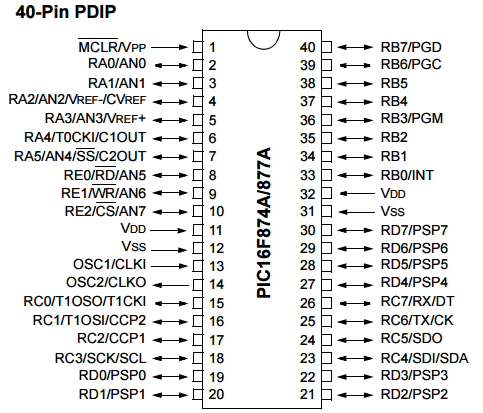
As shown above PIC16F877 has 5 basic input/output ports. They are usually denoted by PORT A (R A), PORT B (RB), PORT C (RC), PORT D (RD), and PORT E (RE). These ports are used for input/output interfacing. In this controller, “PORT A” is only 6 bits wide (RA-0 to RA-5), ”PORT B” , “PORT C”,”PORT D” are only 8 bits wide (RB-0 to RB-7,RC-0 to RC-7,RD-0 to RD-7), ”PORT E” has only 3 bit wide (RE-0 to RE-2).
All these ports are bi-directional. The direction of the port is controlled by using TRIS(X) registers (TRIS A used to set the direction of PORT-A, TRIS B used to set the direction for PORT-B, etc.). Setting a TRIS(X) bit ‘1’ will set the corresponding PORT(X) bit as input. Clearing a TRIS(X) bit ‘0’ will set the corresponding PORT(X) bit as output.
For our project we have to make the pin RB3 of PORT B as output so that our LED can be connected to it. Here is code for LED blinking with PIC microcontroller:
#include <xc.h>
#define _XTAL_FREQ 20000000 //Specify the XTAL crystal FREQ
void main() //The main function
{
TRISB=0X00; //Instruct the MCU that the PORTB pins are used as Output.
PORTB=0X00; //Make all output of RB3 LOW
while(1)    //Get into the Infinite While loop
    {
    RB3=1; //LED ON
    __delay_ms(500);   //Wait
    RB3=0; //LED OFF
    __delay_ms(500);   //Wait
    //Repeat.
    }
}
First we have specified the external Crystal frequency using #define _XTAL_FREQ 20000000. Then in void main() function, we instructed our MCU that we are going to use the RB3 as an output (TRISB=0X00;) pin. Then finally a infinite while loop is used so that the LED blinking goes on forever. In order to blink an LED we have to simply turn it ON and OFF with a noticeable delay.
Once coding is complete, build the Project using Run -> Build Main Project command. This should compile your program. If everything is fine (As it should be) an output Console at the bottom of the screen will show a BUILD SUCCESSFUL message, as shown in the picture below.

Circuit Diagram and Proteus Simulation:
Once we build a Project and if Build is successful, a HEX file would have been generated at the background of our IDE. This HEX file can be found inside the below directory
Desktop\Blink\Blink.X\dist\default\production
It may vary for you if you have saved in some other location.
Now, let us quickly open Proteus that we have installed earlier and create schematics for this project. We are not going to explain on how to do this as it out of the scope of this project. But not to worry, it is explained in the video below. Once you follow the instruction and build the schematics it should look something like this

To simulate the output, click on the play button on the bottom left corner of the screen after loading the Hex file. It should Blink the LED connected to the RB3 of the MCU. If you have any problem in it please watch the video, if still not resolved use the comment section for help.
Now we have made our first project with PIC microcontroller and verified the output using simulation software. Go and tweak around with the program and observe the results. Till we meet on our next project.
Ohh wait!!
In our next project we will be learning how to get this working on a actual hardware. For that we will need the following tools keep them ready. Until then HAPPY LEARNING!!
- PicKit 3
- PIC16F877A IC
- 40 - pin IC holder
- Perf board
- 20Mhz Crystal OSC
- Female and Male Bergstick pins
- 33pf Capacitor - 2Nos
- 680 ohm Resistor
- LED of any color
- Soldering kit.
Complete Project Code
#include <xc.h>

#define _XTAL_FREQ 20000000 //Specify the XTAL crystal FREQ

void main() //The main function

{

TRISB=0X00; //Instruct the MCU that the PORTB pins are used as Output.

PORTB=0X00; //Make all output of RB3 LOW

while(1)    //Get into the Infinite While loop

    {

    RB3=1; //LED ON

    __delay_ms(500);   //Wait

    RB3=0; //LED OFF

    __delay_ms(500);   //Wait

    //Repeat.

    }

}
Comments
Hi Paul,
Hi Paul,
This error is most likely due to the location/directory (The place where you saved them) of your project. Make sure your C file ad the project file is at the same directory.
Follow the video and do the same. To help you much better attach a snap shot of the left side toolbar (The place where your directories are shwon).
Hope it works for you!
Problem with using PIC Kit...
Sir
i am having PIC AVR development kit with PIC32APU1536 microcontroller on it and MP lab IDEv 3.65
in my windows 8.1 laptop but i am not getting how to load code on it i mean using which compiler....?
please help me out
Sorry I cannot help you with ABR
Hi mangesh,
Sorry I cannot help you with this since I have not tried MPLABX with AVR. You can try this question on the foum maybe there you will get answers
Port Status Blink
I wrote a small program using PIC18F4550 for blinking of LED's. I would like to know whether can we observe the blinking of port status like in KEIL after building the program. IDE used is MPLAB X IDE (v 4.15).
Error while Build Main project
While building main project, I get following errors.
make -f nbproject/Makefile-default.mk SUBPROJECTS= .build-conf
make[1]: Entering directory 'C:/Users/HP/MPLABXProjects/Blink.X'
make -f nbproject/Makefile-default.mk dist/default/production/Blink.X.production.hex
make[2]: Entering directory 'C:/Users/HP/MPLABXProjects/Blink.X'
"C:\Program Files (x86)\Microchip\xc8\v1.45\bin\xc8.exe" --pass1 --chip=16F877A -Q -G --double=24 --float=24 --opt=+asm,+asmfile,-speed,+space,-debug,-local --addrqual=ignore --mode=free -P -N255 --warn=-3 --asmlist -DXPRJ_default=default --summary=default,-psect,-class,+mem,-hex,-file --output=default,-inhx032 --runtime=default,+clear,+init,-keep,-no_startup,-osccal,-resetbits,-download,-stackcall,+clib --output=-mcof,+elf:multilocs --stack=compiled:auto:auto "--errformat=%f:%l: error: (%n) %s" "--warnformat=%f:%l: warning: (%n) %s" "--msgformat=%f:%l: advisory: (%n) %s" -obuild/default/production/Blink.p1 Blink.c
Blink.c:1: error: (285) no identifier in declaration
Blink.c:1: warning: (374) missing basic type; int assumed
Blink.c:1: error: (314) ";" expected
Blink.c:21: error: (285) no identifier in declaration
Blink.c:21: error: (314) ";" expected
Blink.c:28: error: (194) ")" expected
Blink.c:28: warning: (371) missing basic type; int assumed
Blink.c:28: error: (984) type redeclared
Blink.c:28: error: (1098) conflicting declarations for variable "_delay" (Blink.c:28)
(908) exit status = 1
nbproject/Makefile-default.mk:106: recipe for target 'build/default/production/Blink.p1' failed
make[2]: Leaving directory 'C:/Users/HP/MPLABXProjects/Blink.X'
nbproject/Makefile-default.mk:90: recipe for target '.build-conf' failed
make[1]: Leaving directory 'C:/Users/HP/MPLABXProjects/Blink.X'
nbproject/Makefile-impl.mk:39: recipe for target '.build-impl' failed
make[2]: *** [build/default/production/Blink.p1] Error 1
make[1]: *** [.build-conf] Error 2
make: *** [.build-impl] Error 2
Please guide me.
Simulation result while running BLINKX.hex
I got following message after running simulation as explained in the video.
X mixed model PIC16.DLL failed to authorise - missing or invalid customer key.
X Real time simulation failed to start.
X Simulation failed due to fatal simulator errors.
Please help me in resolving the issue.
not getting highlighted? did
not getting highlighted? did u try compiling it ? if errors shows up then make sure you have selected the correct IC while opening the editor and also make sure you have added the header files
Pic programming
I am using mplabx v5.5 for pic microcontroller 16f877a. I have followed all the procedures as mentioned. I am pic kit3 as intermediate to program in in PIC. In software, it is showing pickit3 is connected. Target device ID does not match with expected device ID. I have used the controller in the breadboard.
1 pin of PICKIT is connected to pic 1 pin
2 pin is connected to VDD
3 pin is connected to VSS
4 pin is connected to pgd of the controller
5 pin is connected to pgc of the controller
to keep mclr high I have shorted vdd and mclr, and used 10K resistor across mclr and vdd.
I am getting the error as mentioned above.
In settings also I have changed the power. The external power supply also provided. Yet the problem persists. Can u please tell me where the problem exists.
You have not mentioned what
You have not mentioned what error you are getting. The connections seems all good to me
I am getting the error as
I am getting the error as follows
Target device ID does not match with the expected device ID
check your ICSP connection
check your ICSP connection and also make sure you have selected the right MCU
All my ICSP connections are
All my ICSP connections are correct, and I used MCU 16f877a
Frequency oscillator
Hi can we use a 16MHz frequency oscillator with 22pf capacitors for this PIC circuit?
Configuration getting easier...
Learned how to use the configuration bits screen...much easier.
Errors in running Proteus simulation
I seem to get the following error messages when I try to run the simulation in Proteus.
PROSPICE 8.08.00 (Build 27367) (C) Labcenter Electronics 1993-2019.
mixed model PIC16.DLL failed to authorize - Missing or invalid Customer Key.. [U1]
Loaded netlist 'C:\Users\Eric\AppData\Local\Temp\LISA6525.SDF' for design 'Blink.pdsprj'
Real Time Simulation failed to start.
Simulation FAILED due to fatal simulator errors.
How might I resolve these errors? Is this what happens when you use the demo version of the software?
Hi I'm using Proteus 8 and
Hi I'm using Proteus 8 and have the following error:
mixed model PIC16.DLL failed to authorize - Missing or invalid Customer Key.. [U1]
How do I get the customer key?

I am running MPLAB X, V3.65, on windows 10, I have followed your very detailed ifo and video for the Blink project, and all is well until I try and build the project, when I get the following 141 error message:
highlighted below with *************************Error starts here*******************************
CLEAN SUCCESSFUL (total time: 143ms)
make -f nbproject/Makefile-default.mk SUBPROJECTS= .build-conf
make[1]: Entering directory 'C:/Users/Paul's/MPLABXProjects/Blink/Blink.X'
make -f nbproject/Makefile-default.mk dist/default/production/Blink.X.production.hex
make[2]: Entering directory 'C:/Users/Paul's/MPLABXProjects/Blink/Blink.X'
"C:\Program Files (x86)\Microchip\xc8\v1.42\bin\xc8.exe" --pass1 --chip=16F877A -Q -G --double=24 --float=24 --opt=+asm,+asmfile,-speed,+space,-debug,-local --addrqual=ignore --mode=free -P -N255 --warn=-3 --asmlist -DXPRJ_default=default --summary=default,-psect,-class,+mem,-hex,-file --output=default,-inhx032 --runtime=default,+clear,+init,-keep,-no_startup,-osccal,-resetbits,-download,-stackcall,+clib --output=-mcof,+elf:multilocs --stack=compiled:auto:auto "--errformat=%f:%l: error: (%n) %s" "--warnformat=%f:%l: warning: (%n) %s" "--msgformat=%f:%l: advisory: (%n) %s" -obuild/default/production/Blink.p1 Blink.c
************************Error starts here**********************************
build/default/production\Blink.pre:0: error: (141) can't open temporary file "C:\Users\Pauls\AppData\Local\Temp\s8pg.5
": No such file or directory
(908) exit status = 1
nbproject/Makefile-default.mk:106: recipe for target 'build/default/production/Blink.p1' failed
make[2]: Leaving directory 'C:/Users/Paul's/MPLABXProjects/Blink/Blink.X'
nbproject/Makefile-default.mk:90: recipe for target '.build-conf' failed
make[1]: Leaving directory 'C:/Users/Paul's/MPLABXProjects/Blink/Blink.X'
nbproject/Makefile-impl.mk:39: recipe for target '.build-impl' failed
make[2]: *** [build/default/production/Blink.p1] Error 1
make[1]: *** [.build-conf] Error 2
make: *** [.build-impl] Error 2
BUILD FAILED (exit value 2, total time: 729ms)
I would be grateful if you could provide any assistance in rectifying this error. I have not changed any of the directory paths, and accepted all default options on installing. I have googled this Error but found no helpful answers.
Thanks in advance.