

This tutorial is the continuation of the previous tutorial Getting Started with ESP8266 (Part 1). So, to give a small recap, in our previous tutorial we introduced our self to the ESP module and learnt few basics about it. We also made a development board, using a FTDI Serial Adapter Module, which can be easily used to program the ESP module using both using AT commands and Arduino IDE.
In this tutorial we will learn How to use AT commands to operate ESP8266 Wi-Fi Transceiver module. And in the next Tutorial we will learn to Program ESP8266 using Arduino IDE (without Arduino) and Flashing the ESP8266.
Programming the ESP8266 using AT commands:
The first and the easiest way to program your ESP module is by using the AT commands. The letters AT stand for “ATtention “. AT commands are the instructions which can be used to control a specific modem, in our case it is the ESP8266 module. An AT command always starts with the letter AT and is followed by some specific command. The complete list of AT commands which can be used to control and program the ESP8266 is given in documentation by Espressif Systems. The same can be found in the link below.
You can read through documentation to understand what each and every command will do. But, for the purpose of this tutorial I am using only few commands just to check the firmware version of the module and set the module to work in AP (Access Point) mode.
These AT commands can be sent directly from any Serial monitor software (Putty or Arduino) from our computer, basically in order to send these AT commands a Serial communication has to be established between the ESP modules and the Computer. To enable this connection this Rx and Tx pin of the ESP module is connected to the Tx and RX pin of FTDI module respectively as explained in the previous tutorial. So let’s get started…
Also check our various ESP8266 based interesting IoT Projects.
Prerequisites:
You would need the following for this project:
- ESP8266 Module
- FTDI Breakout Board (3.3V)
- Any Serial monitor software like putty or even Arduino will work
- Must have read the Previous tutorial and the above connection should be made
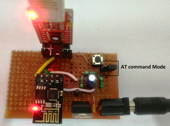
Then the most important step is wiring your ESP module properly. This is very well explained in the previous tutorial. The circuit diagram again is shown here for reference:

Step 1: Install any Serial monitor software. This tutorial uses Arduino Serial Monitor since most of us have experience by using it with Arduino boards.
Step 2: Connect your ESP module and the FTDI module to the development board and power it ON. Make sure the GPIO0 pin is left free and the RST pin is connected to ground momentarily and then left free. We have used jumper switch, in board, to select between programming through AT command and through Arduino IDE. And have used Push button to reset the ESP. If you made the connections as explained in previous tutorial your board should look something like this
Step 3: Connect the FTDI board to your computer and open Device Manager, under COM ports you should see to which COM port your FTDI module is connected to, note it down. Mine is connected to COM20 as shown below.
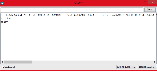
Step 4: Open your Arduino IDE, make sure you are connected to the FTDI COM port (mine is COM20). This can be ensured by checking Tools-> Ports. Now, open your Serial Monitor and select “Both NL&CR” and the baud rate as “115200” as shown at the bottom of the image in the next step.
Note: Your baud rate might also differ based on your Vendor. If 115200 does not work, try 9600 and 38400 and 74880.
Step 5: Make sure your GPIO0 pin is left free (check the switch) and press the reset button. You should see some random values on the Serial monitor and then stop by saying “ready”, as shown in the image below
If you have made it so far, then great!! You can start programming your ESP8266 module using AT commands by using the datasheet. Just to make it more interesting, I will show you how to configure your ESP module in AP+STA mode and see how it works.
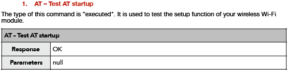
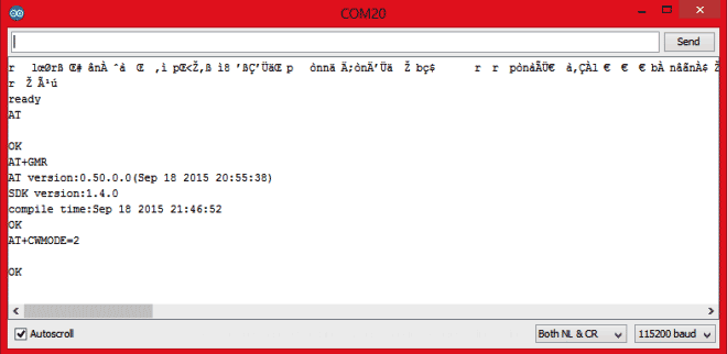
Step 6: The first command that we would use is the AT command. It is just used to check if the start-up is successful. When you type in “AT” and press enter it should reply back with “OK”.
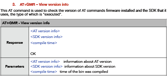
Step 7: The SDK and the firmware version of the module can be check by using the command “AT+GMR”
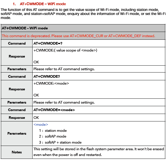
Step 8: As said the ESP module can work in AP mode (Access Point mode), STA mode or both AP and STA mode. Lets run the module in AP mode so that we can check if the working.
Simply send “AT+CWMODE=2” and it will reply you with “OK”
Your serial monitor will look something like below after you have entered the commands
Now you can check if your module is acting as a Access point, by simply trying to connect to its WIFI network. Open your WIFI settings in mobile or laptop and search for the available networks you should find your ESP module listed as shown below. Mine is named as ESP_A3A3E7
The complete steps and its working is also shown in the video below.
So let us stop this for now, in next tutorial we will see “How we can program the module using Arduino IDE and How to Flash the ESP8266 memory”.
Don’t forget to check our other ESP8266 based Projects.
Comments
Thanks arun,
The tutorial you have been waiting for is published now, you can fnd it here
https://circuitdigest.com/microcontroller-projects/programming-esp8266-…
Thanks again!!
Hi Sir ,I am using usb to serial converter and esp8266 and also 3.3 v power source..But my esp module gives an error while giving an At command expect command AT.plz help me
Hi Ashwinth, you had given a jumper to switch between AT and Arduino programming. However once Arduino program is uploaded, you said AT programming cannot be done. How do we flash with firmware. i tried various options to get the firmware, appears flashed, but i could not do any AT thru putty or screen monitor of Arduino. Further I am not getting Ready in screen monitor -- it shows junk characters only and does not show ready or respond to any AT calls.. pl suggest
Hi,
I press the push button , and i saw in the serial monitor some stuff but i didn't saw "ready"
also after that i sent "AT "but there is no response at all.
any advice??

Very nice and informative article, now waiting for the 3rd part, 'programming ESP via Arduino'....Thank you..arun