")
Seven segment displays are important display units in Electronics and widely used to display numbers from 0 to 9. It can also display some character alphabets like A,B,C,H,F,E etc. In this tutorial, we are going to learn how to interface a 7 segment display with 8051 microcontroller. We are using AT89S52 microcontroller from 8051 series.
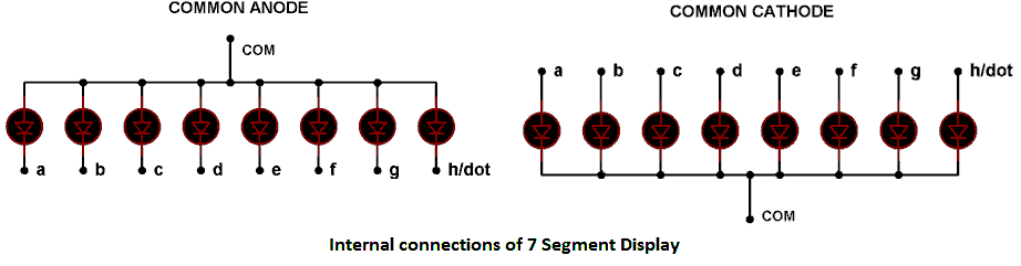
Before interfacing, we should learn about 7 segment display. It’s the simplest unit to display numbers and characters. It just consists 8 LEDs, each LED used to illuminate one segment of unit and the 8th LED used to illuminate DOT in 7 segment display. We can refer each segment as a LINE, as we can see there are 7 lines in the unit, which are used to display a number/character. We can refer each line/segment "a,b,c,d,e,f,g" and for dot character we will use "h". There are 10 pins, in which 8 pins are used to refer a,b,c,d,e,f,g and h/dp, the two middle pins are common anode/cathode of all he LEDs. These common anode/cathode are internally shorted so we need to connect only one COM pin.
There are two types of 7 segment displays: Common Anode and Common Cathode:
Common Anode: In this all the Negative terminals (cathode) of all the 8 LEDs are connected together (see diagram below), named as COM. And all the positive terminals are left alone.
Common Cathode: In this all the positive terminals (Anodes) of all the 8 LEDs are connected together, named as COM. And all the negative thermals are left alone.
Circuit Diagram and Working Expalation
Here we are using common anode type of 7 segment because we need to connect LEDs in reverse. As we know that microcontroller doesn’t provide enough power to glow the LED so we need to connect LED’s cathode to microcontroller pin and LED’s anode to power supply. You can understand this negative logic concept in this article “LED Interfacing with 8051 Microcontroller”. You should also read this article to understand the basic connection of microcontroller like crystal and reset circuitry.

As shown above the circuit diagram for interfacing 7 segment display with 8051 microcontroller, we have connected a,b,c,d,e,f,g,h to pins 2.0 to 2.7 means we are connecting 7 segment to port 2 of microcontroller. Now suppose we want to display 0, then we need to glow all the LEDs except LED which belongs to line “g” (see diagram above), so pins 2.0 to 2.6 should be at 0 (should be 0 to TURN ON the LED as per negative logic) and pin 2.7 and 2.8 should be at 1 (should be 1 to TURN OFF the LED as per negative logic). So the LEDs connected to pins 2.0 to 2.6 (a,b,c,d,e,f) will be ON and LEDs connected to 2.7 and 2.8 (g and h) will be OFF, that will create a “0” in 7 segment. So we need bit pattern 11000000 (Pin 8 is the highest bit so starting from P2.7 to P2.0), and the HEX code for binary 11000000 is “C0”. Similarly we can calculate for all the digits. Here we should note that we are keeping “dot/h” always OFF, so we need to give LOGIC “1” to it every time. A table has been given below for all the numbers while using Common Anode 7 segment.
|
Digit to Display |
h g f e d c b a |
Hex code |
|
0 |
11000000 |
C0 |
|
1 |
11111001 |
F9 |
|
2 |
10100100 |
A4 |
|
3 |
10110000 |
B0 |
|
4 |
10011001 |
99 |
|
5 |
10010010 |
92 |
|
6 |
10000010 |
82 |
|
7 |
11111000 |
F8 |
|
8 |
10000000 |
80 |
|
9 |
10010000 |
90 |
Code Explanation
We have created ms_delay function to provide the delay in milliseconds, this delay is usually provided in any microcontroller program so that microcontroller can complete its internal operation.
Then we have created an array of the hex codes for 0 to 9 (see table above), and finally we have sent the hex codes to the port 2, which is connected to common anode 7 segment. So in this way the numbers are shown on the 7 segment display.
Now we have only 4 ports in microcontroller and what if we want to show the data in more than four 7 segments?? To solve this problem, Multiplexing technique comes into picture. We need to multiplex multiple 7 segment units. Also read interfacing 7 segment display with AVR microcontroller.
Complete Project Code
// Code for 7 Segment Display Interfacing with 8051 Microcontroller (AT89S52)
#include<reg51.h>
void msdelay(unsigned int time)  // Function for creating delay in milliseconds.
{
    unsigned i,j ;
    for(i=0;i<time;i++)
    for(j=0;j<1275;j++);
}
void main()
{
    unsigned char no_code[]={0xC0,0xF9,0xA4,0xB0,0x99,0x92,0x82,0xF8,0x80,0x90}; //Array for hex values (0-9) for common anode 7 segment
    int k;
    while(1)
    {
        for(k=0;k<10;k++)
        {
         P2=no_code[k];
         msdelay(100);
        }
    }
}
Comments
Do you know the coding, when
Do you know the coding, when a switch is pressed, the number count up, +1 only. When the switch pressed again, number count up +1 from previous one...
components used here
May I know components with values used here ?
You need to use Multiplexing
You need to use Multiplexing technique to use more than 1 Seven segment. Get the idea of concept from here 0-99 Counter using AVR Microcontroller, and try writing the code for 8051.
new project
how can I made a project by using seven segment display and keypad binary to decimal converter
i want program for 2 seven
i want program for 2 seven segment comman anode display

THANKS...:)