

In this project we are going to Detect the Colors using TCS3200 Color Sensor Module with Raspberry Pi. Here we used Python code for Raspberry Pi to detect the colors using TCS3200 sensor. To demonstrate the color detection we have used a RGB LED, this RGB LED will glow in the same color, of which the object is presented near the sensor. Currently we have programmed Raspberry Pi to detect only Red, Green and blue colors. But you can program it to detect any color after getting the RGB values, as every color is made up of these RGB components. Check the demo Video at the end.
We have previously read and displayed the RGB values of the colors using the same TCS3200 with Arduino. Before going any further, lets know about TCS3200 Color Sensor.
TCS3200 Color Sensor:
TCS3200 is a Color Sensor which can detect any number of colors with right programming. TCS3200 contains RGB (Red Green Blue) arrays. As shown in figure on microscopic level, one can see the square boxes inside the eye on sensor. These square boxes are arrays of RGB matrix. Each of these boxes contains three sensors for sensing Red, Green and Blue light intensity.
So we have Red, Blue and Green arrays on same layer. So while detecting color we cannot detect all three elements simultaneously. Each of these sensors arrays are to be selected separately one after the other to detect the color. The module can be programmed to sense the particular color and to leave the others. It contains pins for that selection purpose, which has been explained later. There is forth mode that is no filter mode; with no filter mode the sensor detects white light.
We will connect this sensor to Raspberry Pi and will program the Raspberry Pi to provide appropriate response depending on color.
Components Required:
Here we are using Raspberry Pi 2 Model B with Raspbian Jessie OS. All the basic Hardware and Software requirements are previously discussed, you can look it up in the Raspberry Pi Introduction and Raspberry PI LED Blinking for getting started, other than that we need:
- Raspberry Pi with pre-installed OS
- TCS3200 color sensor
- CD4040 counter chip
- RGB LED
- 1KΩ resistor (3 pieces)
- 1000uF capacitor
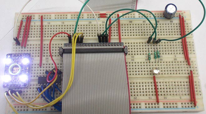
Circuit Diagram and Connections:
The connections which are done for connecting the Color Sensor with Raspberry Pi are given in below table:
|
Sensor Pins |
Raspberry Pi Pins |
|
Vcc |
+3.3v |
|
GND |
ground |
|
S0 |
+3.3v |
|
S1 |
+3.3v |
|
S2 |
GPIO6 of PI |
|
S3 |
GPIO5 of PI |
|
OE |
GPIO22 of PI |
|
OUT |
CLK of CD4040 |
The connections for CD4040 counter with Raspberry Pi are given in below table:
|
CD4040 Pins |
Raspberry Pi Pins |
|
Vcc16 |
+3.3v |
|
Gnd8 |
gnd |
|
Clk10 |
OUT of sensor |
|
Reset11 |
GPIO26 of PI |
|
Q0 |
GPIO21 of PI |
|
Q1 |
GPIO20 of PI |
|
Q2 |
GPIO16 of PI |
|
Q3 |
GPIO12 of PI |
|
Q4 |
GPIO25 of PI |
|
Q5 |
GPIO24 of PI |
|
Q6 |
GPIO23 of PI |
|
Q7 |
GPIO18 of PI |
|
Q8 |
No connection |
|
Q9 |
No connection |
|
Q10 |
No connection |
|
Q11 |
No connection |
Below is the full circuit diagram of Interfacing Color Sensor with Raspberry Pi:

Working Explanation:
Every color is made up of three colors: Red, Green and Blue (RGB). And if we know the intensities of RGB in any color, then we can detect that color. We have previously read these RGB values using Arduino.
Using TCS3200 Color Sensor, we cannot detect Red, Green and Blue light at the same time so we need to check them one by one. The color which needs to be sensed by the Color Sensor is selected by two pins S2 and S3. With these two pins, we can tell the sensor which color light intensity is to be measured.
Say if we need to sense the Red color intensity then we need to set both pins to LOW. After getting the RED light measured, we will set S2 LOW and S3 HIGH to measure the blue light. By sequentially changing the logics of S2 and S3 we can measure Red, Blue and Green light intensities, according to the below given table:
|
S2 |
S3 |
Photodiode Type |
|
Low |
Low |
Red |
|
Low |
High |
Blue |
|
High |
Low |
No filter (white) |
|
High |
High |
Green |
Once the sensor detects the intensities of RGB components, the value is sent to the control system inside the module as shown in the figure below. The light intensity measured by array is sent to the Current to Frequency converter inside the module. The frequency converter generates a square wave whose frequency is directly proportional to the value sent by the array. With higher value from the ARRAY, Current to Frequency converter generates the square wave of higher frequency.
The output signal frequency by the color sensor module can be adjusted to four levels. These levels are selected by using S0 and S1 of sensor module as shown in below figure.
|
S0 |
S1 |
Output Frequency Scaling (f0) |
|
L |
L |
Power Down |
|
L |
H |
2% |
|
H |
L |
20% |
|
H |
H |
100% |
This feature comes in handy when we are interfacing this module to the system with low clock. With Raspberry Pi we will select 100%. Remember here, under the shade the Color Sensor Module generates a square wave output whose maximum frequency is 2500Hz (100% scaling) for each color.
Although the module provides output square wave whose frequency is in directly proportion to light intensity falling on its surface, there is no easy way to calculate the light intensity of each color by this module. However we can tell whether the light intensity is increasing or decreasing for each color. Also we can calculate and compare the Red, Green, Blue values to detect the color of light or color of object preset at the surface of module. So this is more of Color Sensor module rather than Light Intensity Sensor module.
Now we will feed this Square wave output to the Raspberry Pi but we cannot give it directly to PI, because Raspberry Pi does not have any internal counters. So first we will give this output to CD4040 Binary Counter and we will program Raspberry Pi to take the frequency value from the counter at periodic intervals of 100msec.
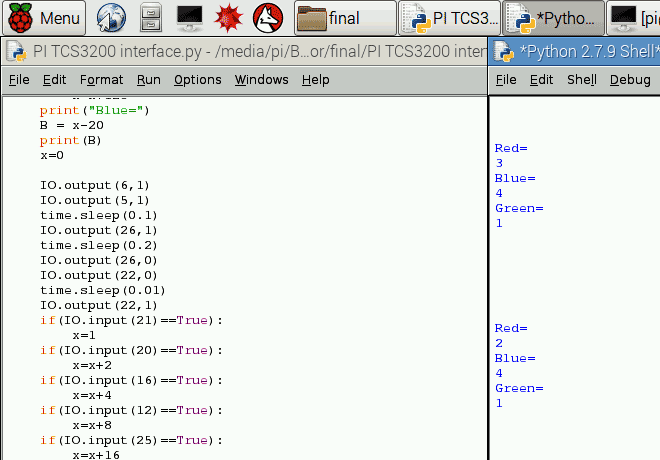
So the PI reads a value of 2500/10 = 250 max for each RED, GREEN and BLUE color. We have also programmed Raspberry Pi to print these values representing the light intensities on the screen as shown below. The values are subtracted from the default values to reach to zero. This comes in handy while deciding the color.
Here the default values are the values of RGB, which have taken without placing any object in front of sensor. It depends upon the surrounding light conditions and these values can differs according to surroundings. Basically we are calibrating the sensor for standard readings. So first run the program without placing any object and note the readings. These values will not be near zero as there will be always some light falling on the sensor no matter where you place it. Then subtract those readings with the readings which we will get after placing an object to test. This way we can get standard readings.
Raspberry Pi is also programmed to compare the R, G and B values to determine the color of the object placed near the sensor. This result is shown by glowing RGB LED connected to Raspberry Pi.
So in nutshell,
1. The module detects the light reflected by the object placed near the surface.
2. The Color Sensor Module provides output wave for R or G or B, chosen sequentially by Raspberry Pi through the Pins S2 and S3.
3. CD4040 Counter takes the wave and measures the frequency value.
4. PI takes the frequency value from the counter for each color for every 100ms. After the taking the value each time PI resets the counter to detect the next value.
5. Raspberry Pi prints these values on screen and compares these values to detect the object color and finally glow the RGB LED in appropriate color depending on color of object.
We have followed the above sequence in our Python Code. Full program is given below with a Demonstration Video.
Here Raspberry Pi is programmed to detect only three colors, you can match the R, G and B values accordingly to detect more colors of your liking.
Complete Project Code
#working
import time
import RPi.GPIO as IO
IO.setmode (IO.BCM)
IO.setwarnings(False)  #do not show any warnings
x=0
IO.setup(6,IO.OUT      #pins 6,5,… are set as output
IO.setup(5,IO.OUT)
IO.setup(27,IO.OUT)
IO.setup(17,IO.OUT)
IO.setup(13,IO.OUT)
IO.setup(22,IO.OUT)
IO.setup(26,IO.OUT)
IO.setup(21,IO.IN)     #pins 21,20… are set as input
IO.setup(20,IO.IN)
IO.setup(16,IO.IN)
IO.setup(12,IO.IN)
IO.setup(25,IO.IN)
IO.setup(24,IO.IN)
IO.setup(23,IO.IN)
IO.setup(18,IO.IN)
while 1:
    IO.output(6,0)     #choose red array by putting S2 and S3 low
    IO.output(5,0)
    time.sleep(0.1)
    IO.output(26,1)    #reset counter one time
    time.sleep(0.2)
    IO.output(26,0)
    IO.output(22,0)    #enable output of module for 100msec for counter to read frequency
    time.sleep(0.01)
    IO.output(22,1)
    if(IO.input(21)==True):
        x=1
    if(IO.input(20)==True):
        x=x+2
    if(IO.input(16)==True):
        x=x+4
    if(IO.input(12)==True):
        x=x+8
    if(IO.input(25)==True):
        x=x+16
    if(IO.input(24)==True):
        x=x+32
    if(IO.input(23)==True):
        x=x+64
    if(IO.input(18)==True):
        x=x+128
    print("Red=")     #detect value counted by counter
    R = x-50
    print(R)
    x=0
    IO.output(6,0)    #choose blue array
    IO.output(5,1)
    time.sleep(0.1)
    IO.output(26,1)   #reset counter one time
    time.sleep(0.2)
    IO.output(26,0)
    IO.output(22,0)   #enable output of module for 100msec for counter to read frequency
    time.sleep(0.01)
    IO.output(22,1)
    if(IO.input(21)==True):
        x=1
    if(IO.input(20)==True):
        x=x+2
    if(IO.input(16)==True):
        x=x+4
    if(IO.input(12)==True):
        x=x+8
    if(IO.input(25)==True):
        x=x+16
    if(IO.input(24)==True):
        x=x+32
    if(IO.input(23)==True):
        x=x+64
    if(IO.input(18)==True):
        x=x+128
    print("Blue=")    #detect value counted by counter
    B = x-20
    print(B)
    x=0
    IO.output(6,1)    #choose green array
    IO.output(5,1)
    time.sleep(0.1)
    IO.output(26,1)   #reset counter one time
    time.sleep(0.2)
    IO.output(26,0)
    IO.output(22,0)   #enable output of module for 100msec for counter to read frequency
    time.sleep(0.01)
    IO.output(22,1)
    if(IO.input(21)==True):
        x=1
    if(IO.input(20)==True):
        x=x+2
    if(IO.input(16)==True):
        x=x+4
    if(IO.input(12)==True):
        x=x+8
    if(IO.input(25)==True):
        x=x+16
    if(IO.input(24)==True):
        x=x+32
    if(IO.input(23)==True):
        x=x+64
    if(IO.input(18)==True):
        x=x+128
    print("Green=")   #detect value counted by counter
    G=x-42
    print(G)
    x=0
    print
    print
    print
    print
    print
    print
    if((R>=B+10)and(R>=G+10)):    #if RED color intensity is high light RED led
        IO.output(17,0)
    elif((G>=B+10)and(G>=R+10)):  #if GREEN color intensity is high light GREEN led
        IO.output(13,0)
    elif((B>=R+10)and(B>=G+10)):  #if BLUE color intensity is high light BLUE led
        IO.output(27,0)
    time.sleep(2)    #after 2 sec turn off LEDs
    IO.output(17,1)
    IO.output(13,1)
    IO.output(27,1)

Hi,
I tried the color sensor module. I have used Raspberry Pi, OSEPP color sensor, RGB led and CD4040BE chip for testing this module. However, I get negative RGB values and the sensor doesn't detect colors properly. When I run the python script, LED glows and emits blue color. Could you please share any links about how the frequency is measured?
Regards,
Pavani