
An edge avoider robot is quite similar to my previous project "Line Follower Robot". This 8051 microcontroller based robot detects an edge and avoids it by turning or stopping. Let us see how can we design a edge avoider robot easily.
Concept of Edge Avoider Robot
Concept of Edge Avoider robot is same as line follower. In these types of robots, we generally use behaviour of light at black and white surface. When light fall on a white surface it will almost full reflects and in case of black surface light is absorbed by black surface. This behaviour of light is used in an line follower robot as well as edge avoider robot.
Here we have used IR transmitter and receiver also called photo diodes are used for sending and receiving light. IR transmits infrared lights. When infrared rays falls on any surface except black or much dark surfaces, it’s reflected back and catched by photodiode and generates some voltage changes. When IR light falls on black surface, light is absorbed by the black surface and no rays reflect back, resultantly photo diode doesn't receive any light or rays.
Here in this Edge Avoider robot when sensor senses white surface then microcontroller gets 0 as input and when senses black line controller gets 1 as input.
Circuit Diagram and Working Explanation
We can devide the Edge Avoider Robot project into three different sections that are sensor section, control section and driver section.
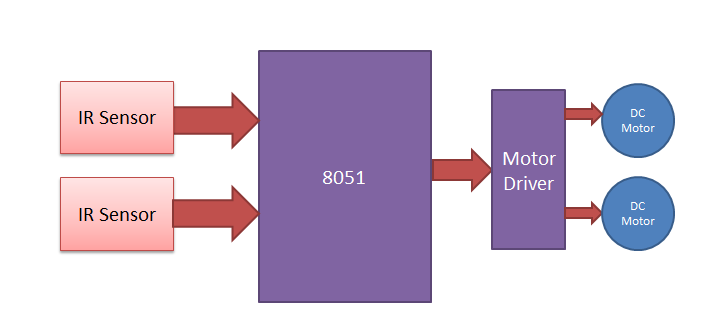
Sensor section: This section contains IR diodes, potentiometer, Comparator (Op-Amp) and LEDs. Potentiometer is used for setting reference voltage at comparator’s one terminal and IR sensors are used to sense the line and provide a change in voltage at comparator’s second terminal. Then comparator compares both voltages and generates a digital signal at output. Here in this circuit we uses two comparators for two sensors. LM 358 is used as comparator. LM358 has inbuilt two low noise Op-amp.
Control Section: 8051 microcontroller is used for controlling whole the process of line follower robot. The outputs of comparators are connected to pin number P0.0 and P0.1 of 8051. 8051 reads these signals and send commands to driver circuit to drive line follower.
Driver section: Driver section consists motor driver and two DC motors. Motor driver is used for driving motors because microcontroller does not supply enough voltage and current to drive the motor. So we add a motor driver circuit to get enough voltage and current for motor. Microcontroller sends commands to this motor driver and then it drive motors.
Working
Working of this edge avoider robot is quite interesting and same as line follower but difference in the operations after sensing inputs. In this robot when it senses white surface it goes forward and when any one of sensors or both sensors sense no signal or black surface it gets stop and move backward and change its direction and if again it sense white surface than go forward.

Circuit diagram is shown for this edge avoider robot. Output of comparators is directly connected to pin number P0.0 and P0.1 of microcontroller. And motor driver’s input pin 2, 7, 10 and 15 is connected at pin number P2.3, P2.2, P2.1 and P2.4 respectively. And one motor is connected at output pin of motor driver 3 and 6 and another motor is connected at 11 and 14.
In programming first of all we have defined input and output pins. And then in main function we checked inputs and sends output accordingly to output pins for driving motor. There are four conditions in this edge avoider that we read by using 8051 microcontroller. We have used two sensors namely left sensor and right sensor.
Conditions:
Input | Output | Movement Of Robot | ||||
Left Sensor | Right Sensor | Left Motor | Right Motor | |||
LS | RS | LM1 | LM2 | RM1 | RM2 | |
0 | 0 | 1 | 0 | 1 | 0 | Forward |
0 | 1 | 1 | 0 | 0 | 0 | Stop/back/Turn Right |
1 | 0 | 0 | 0 | 1 | 0 | Stop/back/Turn Left |
1 | 1 | 0 | 0 | 0 | 0 | STOP/back/turn left |
We have writen program according to above table conditions.
PCB Layout

Complete Project Code
#include<reg51.h>
sbit ls=P0^0;
sbit rs=P0^1;
void delay(unsigned int time)
{
unsigned i,j;
for(i=0;i<time;i++)
for(j=0;j<1275;j++);
}
#define motor P2
#define forward 0x06
#define backward 0x09
#define turn_left 0x04
#define turn_right 0x02
#define stop 0x00;
void main()
{
    while(1)
    {
     if(ls && rs)
         motor=forward;
     if(!ls && rs)
     {
         motor=stop;
         delay(200);
         motor=turn_left;
         delay(200);
     }
     if(ls && !rs)
     {
         motor=stop;
         delay(200);
         motor=turn_right;
         delay(200);
     }
     else
     {
         motor=stop;
         delay(200);
         motor=turn_left;
         delay(200);
     }
  }
}
Comments
why dont u even give the components list..plz dont post the projects without mentioning componants
Edge Avoiding Robot Using 8051 , i need the components list for that
plz give the components list

Edge Avoiding Robot Using 8051 , i need the components list for that