
You must have seen the Disco Lights or DJ lights, which Turn ON and OFF according to the beats of the music. These lights glow according to the length and pitch (volume) of music beats, basically these are designed to pick the high intensity sound like Bass sound. So these lights follow the high pitch beats in music like drum beats, and Turn ON and OFF according to music pattern. However the sensitivity of the circuit can be increased to pick the low notes too.
Previously we have built Dancing LEDs, which just follow a set pattern and we can only control the speed. Now we are taking this to next level, i.e. Music Operated Dancing LEDs, in which LEDs will flash according to music, just like Disco light, as discussed above. This Musical LEDs circuit is based on transistor BC547. This circuit is very simple and easy to build, it just requires few basic components and it looks very cool.
Components:
- Condenser Mic
- 5- NPN Transistor BC547
- Resistors- 10k (2), 1k (4), 1M (1)
- Ceramic Capacitor 100nF
- 4 – LEDs
- 9v Battery
- Breadboard and connecting wires
Working Explanation:
In this Simple LED Music Light Circuit, condenser mic picks up the sound signals and converts them into voltage levels. These voltage signals are further fed into R-C filter or HIGH PASS filter (R2 and C1), to eliminate the noise from the sound. Further a NPN transistor (Q1- BC547) is used to amplify the signals, from the High Pass filter. Then finally these music signals are given to the array of four transistors. Transistor in this array works as amplifier, and glows the four LEDs according to the sound pattern. This generates a very interesting sequence of dancing LEDs which follows the beats as per their intensity or pitch. We can also add more LEDs with transistor to make it cooler.

We can adjust the sensitivity of MIC by changing the value of R2 and C1, by using the formula for R-C filter:
F = 1/ (2πRC)
F is the cut off frequency, means filter only allow frequency above than F. It can be easily deduced that more the value of RC, less the cut off frequency and higher the sensitivity of MIC. And higher the sensitive of circuit means MIC can pick low volume sounds, hence LEDs can glow on low pitch music also. So by adjusting its sensitivity we can make it less sensitive to reacts only on high note beats or we can also make it more sensitive to react on every little beat in the music. Here we have set its sensitivity at moderate level.
Condenser Mic should be connected properly in the circuit, according to its polarity. To determine the polarity of MIC one should look at mic terminals, the terminal which have three soldering lines, is the negative terminal.
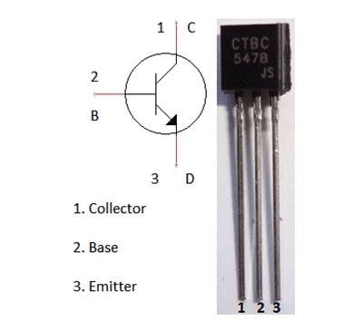
Transistor BC547 is a NPN transistor, which is used as a Amplifier here. NPN transistor acts as a open switch when there is no voltage applied on its Base (B) and it acts as closed switch when these is some voltage at its base. Generally 0.7 volt is enough to get it fully conducted.
Comments
Transistor is used as Amplifier here, please learn more about Transistor.
im trying to get mine to work and have done all the hook ups and it still isnt workign. please help
In this circuit transistor acts as switch. however, I use 220ohms resistor instead of 1kohms and I added another resistor(also 220ohms) between the collector of Q1 and base of Q2, then it works.
I did the same connections as above but the LEDs are glowing without music too.Can anyone help out?.
I want to know how connections are done. Especially the bases of transistor.
Please reply fast
Reduce the value of 1 M resistor or use variable resistor instead and adjust the sensitivity.
I reduced 1M ohm resistor to 1Kohm then too the leds r glowing on its own ...Any solution???
as u r connected Microphone The Small Audio Inputs Are Also Causing THe LED Action.Insted Of Mic U Can Also Add A Audio Input Signal For A Perfact Action.,
The circuit worked perfectly :) , but i want to know what will happen if we replaced the MIC with a high voltage signal.
Not getting your question.
How it's working plz tell me give circuit diagram and with connections also ur circuit diagram plz tell me
can we use transister BC548 ?
This circuit is really great and cool. I just wanna know if it is ok to use low pass filter instead of high pass filter to make the LEDs blink on and off to the bass.
No, you should only use High pass filter. Low pass filter is opposite of High pass. High pass filter allow signal above the selected cut off frequency, whereas Low pass filter allows signal below than cut off frequency.
It does not make any sense to have a HP filter as the 'beat' is in the lower frequencies. Further a HP lowers sensitivity
who current through in transistor
if i want to increase no of led's ......wht chnges comes in circuit ? should i have to increase voltage ?
For a 9v battery you can glow up to 25-30 LEDs, more the LEDs, faster will Battery run out.
Appreciate you sharing, great forum.Much thanks again. Winley
I was just wondering if it is ok to use other types of non-electrolytic capacitor instead of ceramic capacitor? Thank you
What's the function of R1?
Resistor R1 (10k) has been used as a Pull up resistor to connect Condenser mic to the positive supply voltage, to provide the power to the mic.
R1 sets the voltage for the condenser mic. This type of mic requires a power supply
hi! Hey I was wondering if instead a mic I could use a jack, a mono one of course....also, if I wanna turn brighter leds ill just lower the 1k resistors, no?
Thanks, nice project btw!
hey,
which type of mic we can used , if we are not using condensor mic?
what is the total cost of this ?
could you propose me a circuit total cost under Rs.50.
Please i want to know the precise values of resistor R1-R7 please
can you teach us how to make this kind of project.steps please
can you tell me what's the role of BC 547 npn transistor in the circuit and how it is happing I.e, the LEDs r
glowing in presence of music
what actually happening when supply voltage is given to the circuit
can u plz provide the ckt digram
hai , can we extend the circuit , i mean can we increase the no of leds used in the circuit and driving capacity
Could you give me the spec for the mic or ideally a good place to source them
What is the value of R2
can I use 1watt leds fr dis ??
A great site and an interesting Q&A. I can't say more than to say thanks..
I have gotten all the questions.
I love the comprehensive explanation from the cct analysis.
Kudos to you..
I have bookmark you already
We have built the circuit but the leds are unresponsive to music - they flash if we clap our hands beside the mic but otherwise nothing. Circuit has been built using exact components described and follows exactly the same layout. Any suggestions?
Hy CLaire ,I have the same problem with my circuit .. I designed a pcb board ... and all connection are good beacause how you say if i clap my hand the microphone sensing this , and for a few part of a second , leds flash. I don't know what's the problem ... have you solved this problem ? if anyone can help me with this problem I could offer him the pcb replacement (board) .
Tank you a lot . All the best.
There are several design issues with this circuit;
1) insufficient gain - a single transistor can not provide enough gain for the transistors that drive the LEDs
2_ the LED driving transistors are unbiased and so need at least 0.65V to turn-on
3) a HP filter makes no sense as low frequenies have more 'power' and the beat
In your case it sounds (no pun intended) like it is "working" but you want the light extended. A capacitor connected to Q1's Collector and Ground - say 10 uF - might help. Otherwise a 'pulse stretcher' circuit is needed.
There are several design issues with this circuit;
1) insufficient gain - a single transistor can not provide enough gain for the transistors that drive the LEDs
2_ the LED driving transistors are unbiased and so need at least 0.65V to turn-on
3) a HP filter makes no sense as low frequenies have more 'power' and the beat
I want to make the circuit more simple because i want to demonstrate in front of primary school student. If I reduce the number of led its will effect the circuit or not?
Should be no problem. Leds with Resistor and Transistor are set in parallel, therefore you can add or remove as you want.
Led1 + Q2 + R4 = 1 group
Led2 + Q3 + R5 = 1 group
Led3 + Q4 + R6 = 1 group
Led4 + Q5 + R7 = 1 group
Just make sure you add or remove a complete group when adding or removing leds.
please explain how to make connection in this circuit please teach me any one
I wanna this experiment pdf
I did the same thing except instead of 1M ohm I used 1.3 M ohm but my output is not coming.
What if there is no R1 and the capasitor connected to the ground and the mic directly connected to the battery? Is this circuit still work?
I have exactly represented the circuit like in the ckt diagram. But The LED's are always on. If i switch the polarity of the LEDS. Then they are OFF, but not recognizing the music input from the mic. (I have used a 1.3M ohm resistor instead of 1M and 104nF capacitor). This shouldn't alter the circuit by a lot should it?
Resistor value is crucial for the circuit work, increasing the resistor value to 1.3M made the circuit highly sensitive and the LEDs will be on even with the sound of air. You can reduce the resistor value but then it will be less sensitive to lower notes of music.
can I add a water dancing circuit , so both circuits work together by using music
Hey.....if i use a 5v battery then what should i do....
I did the same as above ......but led's blink when we touch wires ...but not blink with music.... what i do can any one help me ???
i want to know what the kind of mic is used
I want, I work for this circuit simulation program orcad do not know What kind of MIC is used
Can I use a 2N222 transistor
Plz reply How to use this ckt for 230 volt ac supply.......
Use Relay with Each LED, learn to use Relay here.
What is the maximum no. of led's i can use for a supply of 12v...
i might need 100 leds..
Driving 100 LEDs need approx 2A current (20mA per LED), so you also need to change transistors and other components accordingly.
Ive got all the LEDs hooked up right and everything else i think is correct yet the mic wont cause the leds to do anything but if i remove the transistor from ground all the LEDs light up bright
Kindly tell me about the working of transistors here
LED turns on even no music was played. Tried lowering the 1M ohm resistor value but the same happens. Even tried to remove it completely and it still doesn't work. Can anyone kindly explain whats happening to me please. Thank you.
Put the circuit exactly as shown in the circuit diagram, it will work for sure. Further try replacing the Mic and other components, may be some faulty component is there.
can this circuit be modified to make a audio level indicator??
Check this one: Simple VU Meter Circuit using LM358
Awesome stuff, put together as directed and works awesome... well done... I am thinking on an improvement and adding four seperate transistors on different frequency levels to run four different colours (perhaps for an rgb light strip with required extra circuitry)
what are applications of dancing LEDs
What type of LED's Used in this circuit.plz reply ,Is not worked
im trying to hit 740Hz or F4# . will set up be able to work this?
I understand the amount of ohms needed for the resistors but I'm seeing a lot of variation in the ppm values and percents and all that jazz. Do these values need to be the same for all the resistors, or how do I know what ones to buy when building this circuit?
Value of resistor should be the same, however value of R2 decides the sensitivity of the circuit, more the value of R2 means more the sensitivity to react on low sounds.
Can this circuit employ 3904 NPN's instead of the BC574?
I did as you instructed but when you connect to battery for it just light without music sound
What can I do please
This circuit is working above certain frequency but what to do if I want to set upper frequency too simultaneously in same circuit? Please reply fast...
Hi, I just want to know if the resistors here are 1/4 watts or 1/2 watts?
OHHH yeah!!! it works

what s the role of the transistor here in the circuit ? y we need it ? wat s d main role in tis circuit ?other than transistor can any other element be replaced ?