LED Music Spectrum generates the beautiful lighting pattern according to the intensity of music. It contains many RGB LEDs which not only turns on and off as per the music but also change color according to the music. There are lots of DIY LED Music Spectrum kits available in the market, but here we are going to build this Music Spectrum using NeoPixel RGB LED Matrix and ARM microcontroller. A control panel is fabricated on PCB for this project, check out the whole process below and see this Colorful Music Spectrum in working in the Video given at the end.
Materials Required:
- Flexible 16x16 NeoPixel RGB LED Matrix *2 (link to buy)
- Core Board (PCB by EasyEDA)
- Switching power supply, 5V 40A.
- Audio Line*1, 1 min 2 audio interface*1, Speakers*1.
![]()
How to make a LED Music Spectrum:
Step 1) LED Connection:
Connect two 16*16 RGB LED matrixes by connecting DOU interface of the first LED matrix to the DIN interface of the second one, that’s make a bigger 16*32 RGB LED Matrix.
Step 2) Power Connection:
The operating voltage of my LED Matrix is 5V, so I would like to connect two LED power interfaces into an outlet of a 5V control power. Please take a note that the maximum current of a working LED is 18A, so it is recommended to use an over 40 A control power and choose a thick enough wire to connect it.
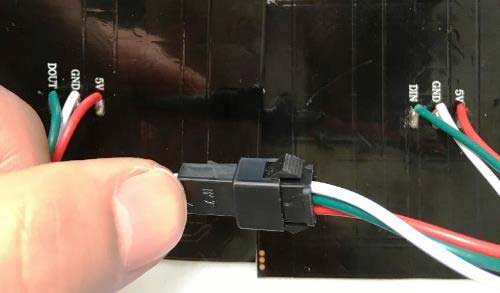
As the picture above shown, the LED power interface is connected to the control power using a thick wire
Step 3) How to make a Control Panel:
A control panel is to receive audio signals which are processed by FFT and then transported to LED matrix display. The controlled LED is a dot-matrix programmed by WS2812b, whose controlling signal frequency is 800KHZ. The timing-controlling diagram is shown as below,
![]()
![]()
Each LED is controlled by 24-bit data with its structure of G7~G0+R7~R0+B7~B0. The data is sent by the principle of higher place first and in accordance with the sequence of GRB.
An amplifier circuit using LM358 has been used in this Music Spectrum as shown below:
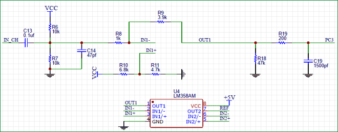
In the diagram, IN_CH is an audio access terminal of a computer and PC3 is the amplified output signal which has been further sent to STM 32. C13, R6 and R7 are grouped into a signal-strengthening circuit, which can raise the signal voltage and turn a negative voltage into a positive one. The circuit following R8 is signal-amplifying one, with its signal strength of PC 3 equal to R9/R8 times of the previous signal before R8. IN 1+ is the end to set the minimum voltage value output from OUT 1.
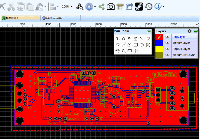
Here we recommend using EasyEDA to design a control panel. EasyEDA is simple and efficient online EDA designing software, by which you can draw a diagram or cut a pattern conveniently. In EasyEDA, the database for the components is huge! You can easily select some of the basic components on the left of the page or search hundreds and thousands of components in their library so it is very easy for you to find what you needed.
Following is the link of my complete circuit diagram and PCB layout, where you can see it very clearly.
https://easyeda.com/tiege/MUSIC_LED_BASE_ON_STM32F103-yEeOdbL75
You can also register an account there so as to download my diagram directly into your account.

Below is a screenshot of PCB layout of LED Music Spectrum circuit from EasyEDA:
Step 4) Prototype PCB:
After finishing the PCB design, click on the icon of Fabrication output above, it will take you to the “PCB order” page. Here you can select the number of PCBs, no of copper layers, PCB thickness, copper weight, and even the PCB color. After you have selected all of the options, click “Save to Cart” and complete your order, to receive your PCBs within few days.
Here are the PCB boards after manufacturing; the quality of PCBs is quite impressive. The traces are routed precisely and all of the printing is very clear.
![]()
Then components are soldered on the PCB as shown in the below image, this completes our Control Panel for Music Spectrum.
Circuit Diagram and working Explanation:

Connect the computer audio cable (3.5mm jack) into the beta version of the welded interface, and then open the computer music (It is possible that you may not hear any sound of the computer music after inserting the audio line. Under such circumstance, we can use a 1-turn-two connector to transform the computer audio output into two channels output. One channel is connected to the core-PCB-board while the other to a speaker.
![]()
This is a connecting diagram of the system, where the core-board is powered by a computer USB and connected by an audio output interface. The other interface of the computer audio output is connected to an external speaker. It is feasible that the signal line of the lattice-control interface is connected with the ground wire and the dot- matrix DIN and GND.
Now you just need to upload the below given Program Code into STM32F103RBT6 ARM Microcontroller and you can see the colorful music spectrum.
So here we have built the LED Music Spectrum with RGB LEDs, hope you like it and you can also change the program to make the music spectrum more splendid.
Complete Project Code
/*
Main.c
*/
#include "delay.h"
#include "sys.h"
#include "usart.h"
#include "adc.h"
#include "stm32_dsp.h"
#include <math.h>
#include "pwm.h"
#include "dma.h"
/* Private typedef -----------------------------------------------------------*/
/* Private define ------------------------------------------------------------*/
#define NPT 64 //FFT Sampling number
#define TIMING_ONE 68
#define TIMING_ZERO 32
uint32_t ADC_DataNum=0; //ADC Sampling number
volatile uint8_t ADC_TimeOutFlag=1; //ADC Time sampling time¡®s ok
extern __IO uint16_t ADCConvertedValue; //ADC Sampling value
long lBUFMAG[NPT+NPT/2]; //Storing the data after modeling
long lBUFOUT[NPT];//FFT Output sequence
long lBUFIN[NPT];//FFT Output sequence
u8 count=1;
u8 count_old=5;
uint16_t colour_time=0;
u8 count_time=0;
uint16_t LED_BYTE_Buffer[14400];
uint8_t write[3]={0x0f,0x0f,0x0f};
uint8_t Green[3]={0x00,0x0f,0x00};
uint8_t red[3]={0x0f,0x00,0x00};
uint8_t blue[3]={0x00,0x00,0x0f};
uint8_t sendbuff[514][3]={0};//100 LED
uint16_t DisplayDataBuf[32]={0}; //Display buffer
uint8_t fftHightRedBuf[NPT/2]={0}; // Red frequency column height array
void powerMag(long nfill)
{ int32_t lX,lY;
uint32_t i;
for (i=0; i < nfill; i++)
{
lX= (lBUFOUT[i]<<16)>>16; /* sine_cosine --> cos */
lY= (lBUFOUT[i] >> 16); /* sine_cosine --> sin */
{
float X= 64*((float)lX)/32768;
float Y = 64*((float)lY)/32768;
float Mag = sqrt(X*X+ Y*Y)/nfill; //The first Sum of squares and root
lBUFMAG[i] = (long)(Mag*65536);
}
}
}
void WS2812_send(uint8_t (*color)[3], uint16_t len)
{
uint8_t i;
uint16_t memaddr;
uint16_t buffersize;
buffersize = (len*24)+43; // number of bytes needed is #LEDs * 24 bytes + 42 trailing bytes
memaddr = 0; // reset buffer memory index
while (len)
{
for(i=0; i<8; i++) // GREEN data
{
LED_BYTE_Buffer[memaddr] = ((color[len][1]<<i) & 0x0080) ? TIMING_ONE:TIMING_ZERO;
memaddr++;
}
for(i=0; i<8; i++) // RED
{
LED_BYTE_Buffer[memaddr] = ((color[len][0]<<i) & 0x0080) ? TIMING_ONE:TIMING_ZERO;
memaddr++;
}
for(i=0; i<8; i++) // BLUE
{
LED_BYTE_Buffer[memaddr] = ((color[len][2]<<i) & 0x0080) ? TIMING_ONE:TIMING_ZERO;
memaddr++;
}
len--;
}
LED_BYTE_Buffer[memaddr] = ((color[0][2]<<8) & 0x0080) ? TIMING_ONE:TIMING_ZERO;
memaddr++;
while(memaddr < buffersize)
{
LED_BYTE_Buffer[memaddr] = 0;
memaddr++;
}
DMA_SetCurrDataCounter(DMA1_Channel3, buffersize); // load number of bytes to be transferred
DMA_Cmd(DMA1_Channel3, ENABLE); // enable DMA channel 6
TIM_Cmd(TIM3, ENABLE); // enable Timer 3
while(!DMA_GetFlagStatus(DMA1_FLAG_TC3)) ; // wait until transfer complete
TIM_Cmd(TIM3, DISABLE); // disable Timer 3
DMA_Cmd(DMA1_Channel3, DISABLE); // disable DMA channel 6
DMA_ClearFlag(DMA1_FLAG_TC3); // clear DMA1 Channel 6 transfer complete flag
}
int main(void)
{
uint32_t i=0;
uint16_t k=0;
uint16_t m=0;
uint16_t value=0;
long adcx=0;
delay_init();
NVIC_Configuration();
uart_init(9600);
TIM2_Configuration();
TIM2_NVIC_Configuration();
FFT_RCC_Configuration();
FFT_GPIO_Configuration();
FFT_ADC_Init();
PWM_Init(89,0);
MYDMA_Config(DMA1_Channel3,(u32)&TIM3->CCR3,(u32)LED_BYTE_Buffer,14400);
TIM_Cmd(TIM2, ENABLE);
ADC_SoftwareStartConvCmd(ADC1, DISABLE);
while(1)
{
if(colour_time>=100)
{
colour_time=0;
if(count_time<3)
{
if(Green[0]<0x0f)Green[0]++;
if(Green[0]==0x0f) count_time=1;
if(count_time>=1)
{
if(Green[1]<0x0f)Green[1]++;
if(Green[1]==0x0f) count_time=2;
if(count_time>=2)
{
if(Green[2]<0x0f)Green[2]++;
if(Green[2]==0x0f) count_time=3;
}
}
}
if(count_time>=3)
{
if(Green[0]>0)Green[0]--;
if(Green[0]==0&&Green[1]>0) Green[1]--;
if(Green[1]==0&&Green[2])Green[2]--;
if(Green[2]<0x03) count_time=0;
}
}
if(ADC_TimeOutFlag)
{
ADC_TimeOutFlag=0;
if(ADC_DataNum<NPT)
{
adcx=Get_Adc(13);
lBUFIN[ADC_DataNum]=adcx;
ADC_DataNum++;
}
else
{
TIM_Cmd(TIM2, DISABLE);
ADC_DataNum=0;
cr4_fft_64_stm32(lBUFOUT,lBUFIN,NPT);//the DSP library for FFT
powerMag(NPT);//Calculated frequency amplitude
for(i=0;i<514;i++)
{
for(m=0;m<3;m++)
{
sendbuff[i][m]=0x00;
}
}
for(i=0;i<NPT/2;i++)
{
if(i==0) {if(lBUFMAG[i]>2700)DisplayDataBuf[i]=lBUFMAG[i]-2700;else DisplayDataBuf[i]=10;}
else DisplayDataBuf[i]=lBUFMAG[i];
if(i%2==0) value=i*16+2;
else value=i*16+2-15;
for(m=0;m<3;m++)
{
sendbuff[value][m]=Green[m];
}
if(DisplayDataBuf[i]>1200)k=16;
else if(DisplayDataBuf[i]>1000)k=15;
else if(DisplayDataBuf[i]>900)k=14;
else if(DisplayDataBuf[i]>800)k=13;
else if(DisplayDataBuf[i]>700)k=12;
else if(DisplayDataBuf[i]>600)k=11;
else if(DisplayDataBuf[i]>500)k=10;
else if(DisplayDataBuf[i]>400)k=9;
else if(DisplayDataBuf[i]>300)k=8;
else if(DisplayDataBuf[i]>250)k=7;
else if(DisplayDataBuf[i]>210)k=6;
else if(DisplayDataBuf[i]>180)k=5;
else if(DisplayDataBuf[i]>150)k=4;
else if(DisplayDataBuf[i]>120)k=3;
else if(DisplayDataBuf[i]>100)k=2;
else if(DisplayDataBuf[i]>80)k=1;
else if(DisplayDataBuf[i]>20)k=0;
for(;k>0;k--)
{
for(m=0;m<3;m++)
{
if(i%2==0)
sendbuff[value+k][m]=Green[m];
if(i%2==1)
sendbuff[value-k][m]=Green[m];
}
}
}
delay_ms(50);
WS2812_send(sendbuff,514);
TIM_Cmd(TIM2, ENABLE);
}
}
}
}
void TIM2_IRQHandler(void)
{
if(TIM_GetITStatus(TIM2,TIM_IT_Update)==SET){
TIM_ClearITPendingBit(TIM2,TIM_FLAG_Update);
colour_time++;
ADC_TimeOutFlag=1;
}
}
/*
adc.c
*/
#include "stm32f10x.h"
#include <math.h>
#include "adc.h"
/* Private typedef -----------------------------------------------------------*/
/* Private define ------------------------------------------------------------*/
#define ADC1_DR_Address ((uint32_t)0x4001244C)
/* Private macro -------------------------------------------------------------*/
__IO uint16_t ADCConvertedValue;
/* Private function prototypes -----------------------------------------------*/
/** @defgroup FFT_ADC
* @{
*/
/**
* @brief enable adc1 and clock
* @param None
* @retval None
*/
void FFT_RCC_Configuration(void)
{
#if defined (STM32F10X_LD_VL) || defined (STM32F10X_MD_VL) || defined (STM32F10X_HD_VL)
/* ADCCLK = PCLK2/2 */
RCC_ADCCLKConfig(RCC_PCLK2_Div2);
#else
/* ADCCLK = PCLK2/4 */
RCC_ADCCLKConfig(RCC_PCLK2_Div4);
#endif
/* Enable peripheral clocks ------------------------------------------------*/
/* Enable DMA1 clock */
RCC_AHBPeriphClockCmd(RCC_AHBPeriph_DMA1, ENABLE);
/* Enable ADC1 and GPIOC clock */
RCC_APB2PeriphClockCmd(RCC_APB2Periph_ADC1 | RCC_APB2Periph_GPIOC, ENABLE);
}
/**
* @brief Configure gpio for adc
* @param None
* @retval None
*/
void FFT_GPIO_Configuration(void)
{
GPIO_InitTypeDef GPIO_InitStructure;
/* Configure PC.03 (ADC Channel14) as analog input -------------------------*/
GPIO_InitStructure.GPIO_Pin = GPIO_Pin_3;
GPIO_InitStructure.GPIO_Mode = GPIO_Mode_AIN;
GPIO_Init(GPIOC, &GPIO_InitStructure);
}
/**
* @brief Configure DMA channel
* @param None
* @retval None
*/
u16 Get_Adc(u8 ch)
{
ADC_RegularChannelConfig(ADC1, ch, 1, ADC_SampleTime_239Cycles5 );
ADC_SoftwareStartConvCmd(ADC1, ENABLE);
while(!ADC_GetFlagStatus(ADC1, ADC_FLAG_EOC ));
return ADC_GetConversionValue(ADC1);
}
void FFT_DMA_Init(void)
{
DMA_InitTypeDef DMA_InitStructure;
/* DMA1 channel1 configuration ----------------------------------------------*/
DMA_DeInit(DMA1_Channel1);
DMA_InitStructure.DMA_PeripheralBaseAddr = ADC1_DR_Address;
DMA_InitStructure.DMA_MemoryBaseAddr = (uint32_t)&ADCConvertedValue;
DMA_InitStructure.DMA_DIR = DMA_DIR_PeripheralSRC;
DMA_InitStructure.DMA_BufferSize = 1;
DMA_InitStructure.DMA_PeripheralInc = DMA_PeripheralInc_Disable;
DMA_InitStructure.DMA_MemoryInc = DMA_MemoryInc_Disable;
DMA_InitStructure.DMA_PeripheralDataSize = DMA_PeripheralDataSize_HalfWord;
DMA_InitStructure.DMA_MemoryDataSize = DMA_MemoryDataSize_HalfWord;
DMA_InitStructure.DMA_Mode = DMA_Mode_Circular;
DMA_InitStructure.DMA_Priority = DMA_Priority_High;
DMA_InitStructure.DMA_M2M = DMA_M2M_Disable;
DMA_Init(DMA1_Channel1, &DMA_InitStructure);
/* Enable DMA1 channel1 */
DMA_Cmd(DMA1_Channel1, ENABLE);
}
/**
* @brief Initialization configuration ADC
* @param None
* @retval None
*/
void FFT_ADC_Init(void)
{
ADC_InitTypeDef ADC_InitStructure;
/* ADC1 configuration ------------------------------------------------------*/
ADC_InitStructure.ADC_Mode = ADC_Mode_Independent;
ADC_InitStructure.ADC_ScanConvMode = ENABLE;
ADC_InitStructure.ADC_ContinuousConvMode = ENABLE;
ADC_InitStructure.ADC_ExternalTrigConv = ADC_ExternalTrigConv_None;
ADC_InitStructure.ADC_DataAlign = ADC_DataAlign_Right;
ADC_InitStructure.ADC_NbrOfChannel = 1;
ADC_Init(ADC1, &ADC_InitStructure);
/* ADC1 regular channel13 configuration */
// ADC_RegularChannelConfig(ADC1, ADC_Channel_13, 1, ADC_SampleTime_55Cycles5);
/* Enable ADC1 DMA */
// ADC_DMACmd(ADC1, ENABLE);
/* Enable ADC1 */
ADC_Cmd(ADC1, ENABLE);
/* Enable ADC1 reset calibration register */
ADC_ResetCalibration(ADC1);
/* Check the end of ADC1 reset calibration register */
while(ADC_GetResetCalibrationStatus(ADC1));
/* Start ADC1 calibration */
ADC_StartCalibration(ADC1);
/* Check the end of ADC1 calibration */
while(ADC_GetCalibrationStatus(ADC1));
ADC_SoftwareStartConvCmd(ADC1, DISABLE);
}
/**
* @brief Initialization configuration timer ADC sampling timer
* @param None
* @retval None
*/
void TIM2_Configuration(void)
{
TIM_TimeBaseInitTypeDef TIM_TimeBaseStructure;
RCC_APB1PeriphClockCmd(RCC_APB1Periph_TIM2, ENABLE);
// TIM_OCInitTypeDef TIM_OCInitStructure ;
TIM_DeInit(TIM2);
/* TIM2 configuration */
TIM_TimeBaseStructure.TIM_Period = 25;
TIM_TimeBaseStructure.TIM_Prescaler = 71;
TIM_TimeBaseStructure.TIM_ClockDivision = TIM_CKD_DIV1;
TIM_TimeBaseStructure.TIM_CounterMode = TIM_CounterMode_Up;
TIM_TimeBaseInit(TIM2, &TIM_TimeBaseStructure);
/* Clear TIM2 update pending flag*/
TIM_ClearFlag(TIM2, TIM_FLAG_Update);
/* Enable TIM2 Update interrupt */
TIM_ITConfig(TIM2, TIM_IT_Update, ENABLE);
/* TIM2 enable counter */
TIM_Cmd(TIM2, DISABLE);
}
/**
* @brief Initialization configuration timer timer interrupt
* @param None
* @retval None
*/
void TIM2_NVIC_Configuration(void)
{
NVIC_InitTypeDef NVIC_InitStructure;
/* Enable the TIM1 global Interrupt */
NVIC_InitStructure.NVIC_IRQChannel = TIM2_IRQn;
NVIC_InitStructure.NVIC_IRQChannelPreemptionPriority = 0;
NVIC_InitStructure.NVIC_IRQChannelSubPriority = 1;
NVIC_InitStructure.NVIC_IRQChannelCmd = ENABLE;
NVIC_Init(&NVIC_InitStructure);
}
/*
Pwm.c
*/
#include "pwm.h"
#include "led.h"
void PWM_Init(u16 arr,u16 psc)
{
GPIO_InitTypeDef GPIO_InitStructure;
TIM_TimeBaseInitTypeDef TIM_TimeBaseStructure;
TIM_OCInitTypeDef TIM_OCInitStructure;
RCC_APB1PeriphClockCmd(RCC_APB1Periph_TIM3, ENABLE);
RCC_APB2PeriphClockCmd(RCC_APB2Periph_GPIOB | RCC_APB2Periph_AFIO, ENABLE);
/* Configure PA8(LED0) as input floating */
/*GPIOB0 Configuration: TIM3 channel3*/
GPIO_InitStructure.GPIO_Pin = GPIO_Pin_0;
GPIO_InitStructure.GPIO_Mode = GPIO_Mode_AF_PP;
GPIO_InitStructure.GPIO_Speed = GPIO_Speed_50MHz;
GPIO_Init(GPIOB, &GPIO_InitStructure);
TIM_TimeBaseStructure.TIM_Period = arr;
TIM_TimeBaseStructure.TIM_Prescaler =psc;
TIM_TimeBaseStructure.TIM_ClockDivision = 0;
TIM_TimeBaseStructure.TIM_CounterMode = TIM_CounterMode_Up;
TIM_TimeBaseInit(TIM3, &TIM_TimeBaseStructure);
/* Output Compare Active Mode configuration: Channel1 */
TIM_OCInitStructure.TIM_OCMode = TIM_OCMode_PWM1;
TIM_OCInitStructure.TIM_OutputState = TIM_OutputState_Enable;
TIM_OCInitStructure.TIM_Pulse = 0;
TIM_OCInitStructure.TIM_OCPolarity = TIM_OCPolarity_High;
TIM_OC3Init(TIM3, &TIM_OCInitStructure);
TIM_ARRPreloadConfig(TIM3, ENABLE);
}
Comments
how can i find 4033 ic on easy eda.... I've worked on pcb creator but have difficulty in printing out the circuit.... on two digit object counter
reply me plz i need help
There is More Libraries option in Easyeda, to find more component, chech this article: How to Design a Circuit Board

im happy