All of our Case studies are shared with the clear aim to ensure that the problems that have arisen in one plant can be avoided in other plants, which would lead to a reduction in downtime and increase the productivity and profit margins. This case study is about a frequent Motor Failure problem in the processes industry. You can also check out my other case studies on Electrical maintenance, to read about the different problems that we face in the industry and how we solve it.
In one process plant, the switchboard was designed by some consultant who showed ignorance in the Design & Engineering of protection schemes. This has led to frequent failure of 6.6 kV HT motors without any warnings and abnormality reflected.
We as the Electrical Solution Provider were called upon to identify and rectify the root cause. We were told that few motors have burnt due to overheating/overloading in just 9 -10 months. Initially, we never suspected the Protection Schemes, so we started analyzing the data like motor ratings, CT sizing, transformer ratings, relay settings, load patterns, connected loads, etc.
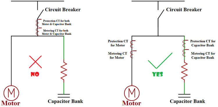
When no checkpoints left, we finally had to examine the Protection Scheme and SLD. This led us to an instant conclusion that it was the wrong protection scheme for Motors that was causing frequent failures and loss of revenue with significant repairing cost and downtime. We were now sure that the common CT and Relays for both motors and capacitor banks were the main cause of frequent failure of motors.
Here is the SLD Representation of the existing/old scheme and corrected Protection Scheme for HT motors with the capacitor bank.

Listed below are major reasons why common protection shouldn’t be used for HT motor with capacitor banks.
A protective relay will not sense the fault properly
In a commonly installed protection scheme for parallel-connected motors and capacitors, current sensed by CT will be less than the actual value. Suppose 3600 kW, 6.6 kV, 384 Amp FLC (0.82 P.F) Slip ring induction motor is running at full load without capacitor bank, then the motor will be taking 384 Amp normally. When connected in parallel with a capacitor bank of 1350 KVAR, loading remains the same i.e. 3600 kW but as the power factor is improved to 0.95, net current reduces to 335 - 340 Ampere. Normally, motor protection relay settings shall be done as per 384 Amp as FLC + permissive overload for a time being. Whereas in the existing protection scheme, the relay will take 340 Amp only. To reach the threshold of 384 Amp, the motor has to run at approximately 4250 KW which is in actual 115% of rated capacity. Now, if the motor keeps running at 115% normally, it will be overheated and shall surely result in the breakdown.
Hard to Detect Faults
Whenever relay trips due to fault, it takes longer time for Engineers to identify the fault/location since common protection for motor and capacitor bank has been used, and hence it increases the downtime as Engineers have to check motors, associated rotor equipment's (if any) in the field and capacitor bank in the substations.
Thus, it can be summed up that the plant authorities should modify the protection scheme by implementing separate protection for motors and capacitor banks. It is also suggested that the motor protection relay settings must be reduced to 88% approximately until the modification in the protection scheme is made.
About the Author
 Avinash Singh is an Electrical Engineer with over 11 years of rich experience in Electrical Maintenance, Installation, Testing, and Commissioning of all major electrical equipment. He is specialized in bringing down Energy Cost of a Plant by reducing electricity bills and increasing energy efficiency. He also reduces plant breakdown costs by implementing proper maintenance activities during routine and shutdown. Through these Case Studies, he shares his experience and challenges faced in his work routine with the readers of Circuit Digest.


