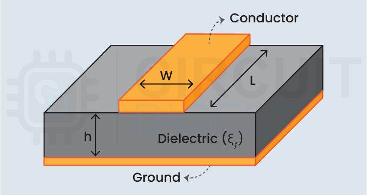
The microstrip line calculator is designed to determine the characteristic impedance and effective dielectric constant of microstrip transmission lines in a PCB, based on physical dimensions and substrate properties. Understanding microstrip impedance calculations is fundamental for RF engineers working with antenna feeds, impedance matching networks, and high-speed digital circuits. The calculator accepts input parameters including relative dielectric constant (εᵣ), track width (mm), track thickness (mm), and dielectric thickness (mm) to compute the characteristic impedance and effective dielectric constant.
The microstrip line impedance calculator utilises the relationship between trace geometry and substrate properties through the microstrip impedance formula. The impedance of the microstrip line is calculated using the following formula:
Z₀ = (377/2π√εₑff) × ln(1 + 4h/Wₑff × X + √(X² + π²/2))
Where W is the physical track width in millimeters(mm)
t is the track thickness in millimeters(mm)
h is the dielectric thickness in millimeters(mm)
π is the mathematical constant pi (≈ 3.14159)
ln represents the natural logarithm function
Example of a Microstrip Impedance Calculator
Calculate impedance for a trace with W = 0.5mm, h = 0.2mm, t = 0.018mm on εᵣ = 3.5 substrate.
First, calculate the effective width:
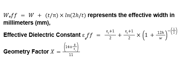
Wₑff = W + (t/π) × ln(2h/t)
Wₑff = 0.5 + (0.018/π) × ln(2×0.2/0.018)
Wₑff ≈ 0.513mm
Calculate εₑff:
εₑff = (εᵣ+1)/2 + (εᵣ-1)/2 × (1 + 12h/W)^(-0.5)
εₑff = 2.25 + 1.25 × (1 + 4.8)^(-0.5)
εₑff ≈ 2.77
Calculate Z₀ (simplified):
Z₀ ≈ 87Ω
Commonly Asked Questions in the Microstrip Line Calculator
⇥ What is a microstrip line?
A microstrip line is a type of electrical transmission line fabricated on a PCB, consisting of a conducting strip separated from a ground plane by a dielectric substrate.
⇥ Why is impedance control important?
Impedance matching prevents signal reflections, ensures maximum power transfer, and maintains signal integrity in high-frequency circuits. Mismatched impedances cause reflections and signal degradation.
⇥ What's the difference between εᵣ and εₑff?
εᵣ is the relative dielectric constant of the substrate material. εₑff (effective dielectric constant) accounts for the fact that some field lines travel through air above the microstrip, resulting in a lower effective value.
⇥ How does trace width affect impedance?
Wider traces have lower impedance, and narrower traces have higher impedance. The relationship is logarithmic, not linear. Doubling the width doesn't halve the impedance.
Explore Related Calculators for High-Frequency PCB and RF Design
Working with RF circuits or high-speed signals? These calculators support impedance matching, power handling, and resonant frequency calculations.

The radar range calculator is designed to determine the theoretical maximum detection distance of a radar system, beyond which the target/object can no longer be detected and analysed, based on the fundamental relationships between transmitted power, antenna parameters, and target properties.

RF Power Conversion Calculator
The RF power conversion calculator is designed to simplify the process of converting between various RF power units commonly used in radio frequency applications and telecommunications systems.
 Calculator")
You can also use this calculator to find out the Power Gain and Voltage Gain from the Decibel value. Just enter the Decibel value and leave Power Gain & Voltage Gain blank, and then hit the Calculate button.
