

An Analog to Digital Converter (ADC) is a type of device that helps process real-world analog signals for digital systems. To understand real-world data like temperature, humidity, pressure, and position, we need transducers that convert these measurements into electrical signals. Since the majority of devices we use at the moment are digital, this conversion becomes necessary, and that's exactly where ADC comes in. Though there are many different types of ADCs out there, in this article, we are going to talk about the successive approximation ADC. The ability to balance speed, accuracy, and efficiency makes the successive approximation ADC one of the most widely used. In an early article, we discussed the basics of ADC with the help of Arduino, and you can see practical ADC implementations in our Arduino ADC tutorial.
Table of Contents
What is a Successive Approximation ADC?
Successive Approximation ADC is the preferred choice for low-cost, medium to high-resolution applications. SAR ADC resolution typically ranges from 8-18 bits, with sample speeds up to 5 mega-samples per second (MSPS). Also, it can be constructed in a small form factor with low power consumption, which is why this type of ADC is used for portable battery-powered instruments.
As the name implies, the successive approximation type ADC uses a binary search algorithm to convert the values, which is why the internal circuitry may be running at several MHz. However, the actual sample rate is much lower due to the Successive Approximation algorithm. We discuss more about this later in this article.
SAR ADC Block Diagram and Circuit Architecture
The cover image shows the basic successive approximation ADC circuit. But to understand the working principle a little better, we are going to use a 4-bit version of it. The image below shows exactly that.
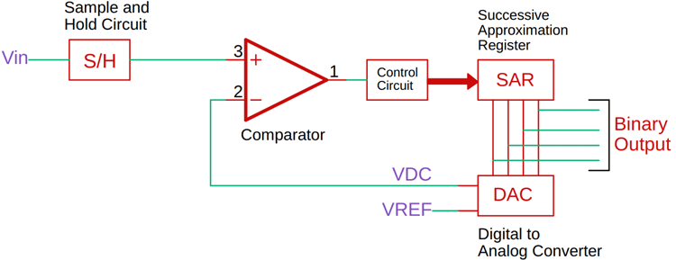
In this SAR ADC block diagram, you can see that the ADC consists of a comparator, a digital-to-analog converter, and a successive approximation register, along with the control circuit. Now, whenever a new conversion starts, the sample and hold circuit samples the input signal. And that signal is compared with the specific output signal of the DAC.
Successive Approximation Register Algorithm Explained
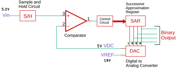
Now, let's say the sampled input signal is 5.8V. The reference of the SAR ADC is 10V. When the conversion starts, the successive approximation register sets the most significant bit to 1 and all other bits to zero. This means the value becomes 1, 0, 0, 0, which means, for a 10V reference voltage, the DAC will produce a value of 5V, which is half of the reference voltage. Now this voltage will be compared to the input voltage, and based on the comparator output, the output of the successive approximation register will be changed. The image below will clarify it more. Further, you can look at a generic reference table for more details on DAC. Previously, we have made many projects on ADCs and DACs; you can check those out for more information.
Step-by-Step SAR ADC Conversion Process
This means if Vin is greater than the output of the DAC, the most significant bit will stay as it is, and the next bit will be set for a new comparison. Otherwise, if the input voltage is less than the DAC value, the most significant bit will be set to zero, and the next bit will be set to 1 for a new comparison. Now, if you see the image below, the DAC voltage is 5V, and as it is less than the input voltage, the next bit before the most significant bit will be set to one, and the other bits will be set to zero. This process will continue until the value closest to the input voltage is reached.
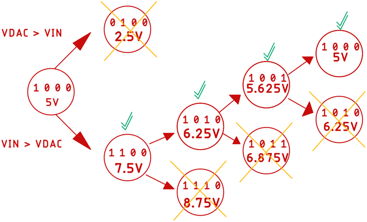
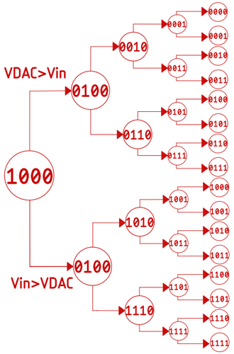
This is how the successive approximation ADC changes 1 bit at a time to determine the input voltage and produce the output value. And whatever the value might be in four iterations, we will get the output digital code from the input value. Finally, a list of all possible combinations for a four-bit successive approximation ADC is shown below.
SAR ADC Specifications: Speed, Resolution & Timing
Conversion Time
In general, we can say that for an N-bit successive approximation type ADC, it will take N clock cycles, which means the conversion time of this ADC will become-
Tc = N x Tclk
*Tc is short for Conversion Time.
And unlike other ADCs, the conversion time of the SAR ADC is independent of the input voltage.
As we are using a 4-bit ADC, to avoid aliasing effects, we need to take a sample after 4 consecutive clock pulses.
Conversion Speed
The typical conversion speed of a successive approximation ADC is around 2 - 5 Mega Samples Per Second (MSPS), but there are a few that can reach up to 10 (MSPS). An example would be LTC2378 from Analog Devices (formerly Linear Technology).
Resolution
The resolution of this type of ADC can be around 8 - 16 bits, but some types can go up to 20 bits. An example would be ADS8900B by Texas Instruments.
Advantages of Successive Approximation ADC
» High accuracy, since the conversion is based on a step-by-step approximation process.
» Low power consumption, which is why it shows up in battery-driven systems.
» Easy to use in practice, because many microcontrollers already have SAR ADCs built in.
» Latency is low. In datasheets, it’s either given in seconds or in conversion cycles. If the data is ready after one cycle, that’s a one-cycle latency. If it takes N cycles, that’s an N-cycle latency.
» It's a good compromise between speed, resolution, and power when compared to flash, sigma-delta, or pipeline ADCs.
» Commonly used and is also very well supported, both as standalone ICs and inside MCUs.
Disadvantages of Successive Approximation ADC
» A drawback is the design complexity and higher production cost compared to simpler architectures.
» The maximum sampling rate is lower than flash ADCs.
» Needs a precise DAC and comparator to function correctly.
» As you push to higher resolution, the successive approximation register itself gets more complex.
» Can be affected by DAC settling time and noise.
Applications of Successive Approximation ADC
As this is a commonly used ADC, it's used for many applications, like biomedical devices that can be implanted in the patient. This type of ADC is used because it consumes very little power. Additionally, many smartwatches and sensors use this type of ADC. You can see SAR ADCs in action in our soil moisture sensor project.
In summary, we can say that the primary advantages of this type of ADC are low power consumption, high resolution, small form factor, and accuracy. This type of character makes it suitable for integrated systems. The main limitation can be its low sampling rate, and the parts required to build this ADC include a DAC and a comparator, and both need to be precise for the ADC to work correctly.
FAQ About Successive Approximation ADCs
Q: Why do microcontrollers almost always have SAR ADCs?
Because they hit the sweet spot. Flash ADCs are lightning fast but eat power and silicon area. Sigma-delta gives crazy resolution, but runs slower. SAR sits between decent speed, good accuracy, and low power. That’s why it shows up in most MCUs.
Q: What kind of resolution are we talking about?
Most MCU SAR ADCs are 10 or 12 bits. If you look at standalone ICs, you’ll find 14, 16, or even 18 bits. Going beyond that usually means sigma-delta territory.
Q: How fast can they actually go?
Usually in the hundreds of kSPS up to a few MSPS. Not in the GHz like flash ADCs, but plenty fast for sensors, control loops, or grabbing analog signals in embedded projects.
Q: What really limits them?
Two big things: the DAC inside and the comparator. If the DAC doesn’t settle fast or the comparator is noisy, accuracy takes a hit. Noise in your board layout can mess with it, too.
Q: So, where do you normally see SAR ADCs used?
Pretty much everywhere. Reading sensors (temperature, pressure, light), medical devices, portable gear that runs on batteries, data acquisition, motor control, you name it.
Q: What is a Successive Approximation ADC Converter?
Wrong question. It’s just Successive Approximation ADC, the “C” already means Converter. Adding “converter” again is a beginner mistake. (And if you’re still unsure, scroll back up and read the article again).
Related ADC and Sensor Projects
Develop a deeper understanding of analog-to-digital conversion and sensor interfacing with these hands-on projects. Explore how flex sensors communicate with Arduino, learn to implement ADC modules in AVR microcontrollers like ATmega16, and experiment with the ADC0808 for 8051-based systems. These projects provide practical insights to complement your knowledge of SAR ADCs and expand your microcontroller skills.

Interfacing Flex Sensor with Arduino
Learn how a flex sensor works with its pinout, and hardware explanation, and also explore how to use it with Arduino. We have given the Arduino flex sensor code, circuit and simulation for easy understanding.

How to use ADC in AVR Microcontroller ATmega16
In this tutorial we will learn What is ADC and How to use ADC in Atmega16. This tutorial includes connecting a small potentiometer to ADC pin of Atmega16 and 8 LED’s are used to display the changing voltage of ADC output value with respect to change in ADC input value.

ADC0808 Interfacing with-8051 microcontroller
Circuit of “Interfacing ADC0808 with 8051” is little complex which contains more connecting wire for connecting device to each other. In this circuit we have mainly used AT89s52 as 8051 microcontroller, ADC0808, Potentiometer and LCD.
