
Compared to DC voltage/very low frequency based comparator applications, the High-Frequency Comparator applications require additional parameters and considerations to provide better signal processing efficiency. Like DC Voltage applications, in High-Frequency applications also, the Op-Amps are being used instead of comparators. But, during high-frequency signal processing, the Op-Amps won’t exhibit the same performance as DC signal input. Before using the Op-Amp for High-Frequency comparator applications, the designer should know how different Op-Amp parameters are getting varied during different Frequency Ranges.
How Op-Amp Performance Differs for DC and High-Frequency Signals?
To understand the high-frequency phenomenon of the Op-Amp, an analysis of the internal structure of the Op-Amp is required. The internal schematic diagram of LM324 Op-Amp is shown in Figure – 1 given below and the Internal Structure of LM339 Comparator is shown in Figure 2.
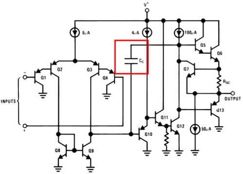
Figure 1: Internal Structure of LM324 Op-Amp
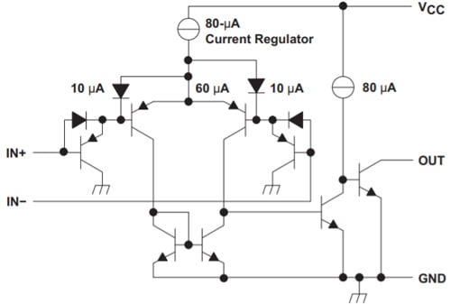
Figure 2: Internal Structure of LM339 Comparator
By comparing the two figures, we can find that along with the transistor and power sources, in Op-Amp there is the presence of a Capacitor whereas, in Comparator, there is no capacitance inside the Circuit. The Capacitor “Cc” present inside the Op-Amp is called “Compensation Capacitor” which defines the high-frequency operation of the given Op-Amp. Among the various high-frequency operational parameters, the Gain is the most important parameter of any op-amp for any application. For Comparator applications, the Op-Amp will use a maximum gain of the Op-Amp, and gain variation due to the frequency is the first notable parameter in Op-Amp for comparator application.
The Gain variation for different frequency signals of LM324 Op-Amp can be found in Open Loop Frequency response curve which is shown in Figure 3.
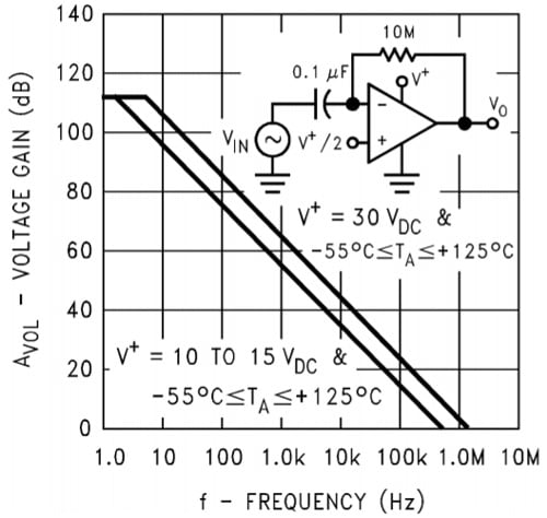
Figure 3: Open Loop Frequency Response
Based on the datasheet curve of Open Loop Frequency response, we can find that the gain of the Op-Amp reduces with the increase in frequency. For less than 10Hz, the Open Loop can provide the maximum gain and around 1MHz frequency, the gain is 0dB (1V/V). In this condition, the output voltage is equal to the difference between Inverting and Non-Inverting terminal voltage only. Also, from the large frequency response of the LM324 Op-amp shown in Figure 4, the output voltage swing is reduced with the increasing frequency. In Figure 4, for 15V Vcc, we can get the maximum output of 13.5V from LM324 Op-Amp whereas, if the signal frequency is 10kHz, the output voltage is only 10V and at 100kHz, it is around 1V. So, like DC applications the comparators can’t be directly replaced by Op-Amp by only considering voltage ratings of the device.
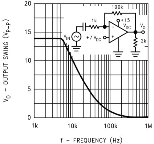
Figure 4: Large Frequency Response
Example Circuit: PWM Generator using Sawtooth and DC reference Signal
The PWM generator circuit is the most widely used circuit in Power Electronics control applications, where the fixed frequency sawtooth waveform is compared with the DC voltage, and based on the magnitude of DC voltage, the PWM duty cycle gets changed.
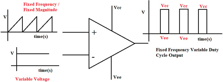
Figure 5: High-Frequency Comparator Application Example
In this example, the non-inverting input (V+) is applied with a sawtooth waveform. The low-level voltage of the Sawtooth (V+) is 0V and the peak voltage is 0.5V. The Inverting input (V-) DC voltage waveform varies between 0V to 0.5V. If the inverting input (V-) is 0V, then the output is always high (Vcc) or 100% Duty cycle. If the Inverting input voltage is greater than or equal to 0.5V then the output voltage is Zero or Vee. In this example, the inverting input voltage is maintained at 0.2V and the response output response with LM339 Comparator is shown in Figure 7 and the respective circuit is shown in Figure 6.
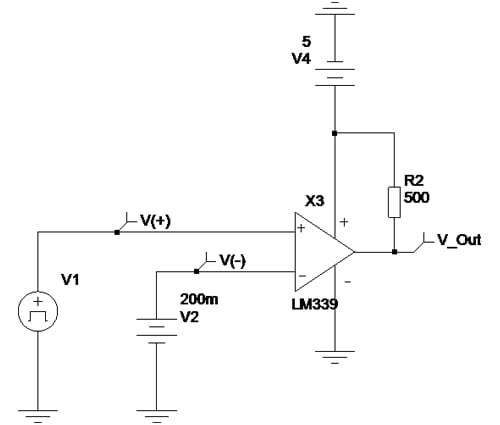
Figure 6: PWM Generator Circuit Using LM339 Comparator
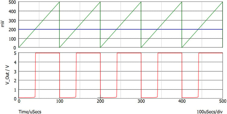
Figure 7: Output Response of PWM Generator Circuit Using LM339 Comparator – 10KHz
The PWM generator circuit with LM339 works better as expected and for 5V Vcc, the output maximum voltage is equal to Vcc and the lower voltage is equal to around 120mV. Based on datasheet specifications, the 120mV nearly matches with a typical low voltage level.
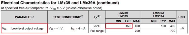
Table 1: LM339 Low-Level Output Voltage Datasheet Specifications
The response of the same circuit with the LM324 Op-amp is shown in the figure given below.
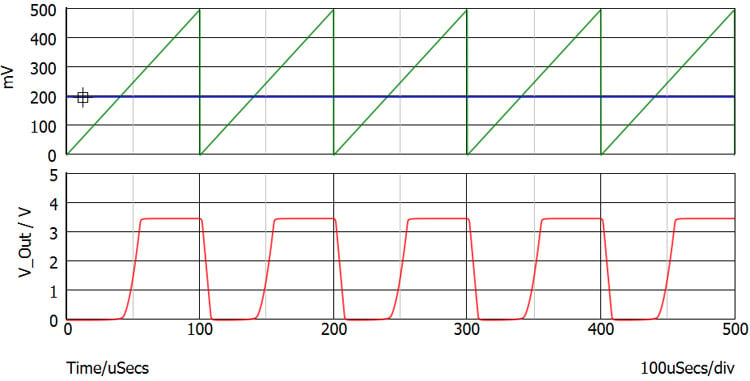
Figure 8: Output Response of PWM Generator Circuit using LM324 Comparator – 10KHz
The comparator circuit implemented with LM324 has produced a different response compared to the response with the LM339 comparator. By putting those two output responses in a single window as shown in Figure 9, we can find two major mismatches.
1) Output Voltage level
2) Rise Time and Fall time of the Op-Amp response
In terms of output voltage level, the comparators always produce the output voltage equal to the Vcc and in rare case, it may be 200mV lesser than or higher than that. But for Op-Amps, the maximum output voltage swing is comparatively lesser than the Vcc. The output voltage swing of LM324 is given in the table given below. As per the datasheet specifications, the maximum output voltage of 5V - Vcc LM324 Op-Amp output is 3.5V only. So, while replacing the comparator with an Op-Amp, the designer must check whether the Op-Amp output voltage swing matches the requirements.
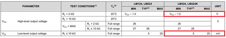
Table 2: LM324 Output Voltage Swing
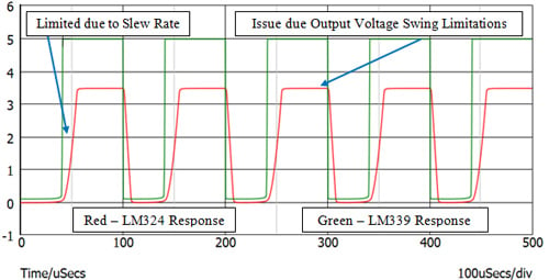
Figure 9: LM339 & LM324 Output Response Comparison – 10KHz
The most important parameter which finalizes the Op-Amp can be used as a comparator is the “Slew Rate” of the Op-Amp. If you are completely new, you can check out this Opamp Slew Rate article to get a better understanding on Slew Rate. The slew rate of Op-Amp is defined as the time taken for the output signal to reach its 10% of magnitude to 90% of magnitude and it is normally denoted in V/us relation. The slew rate of LM324 Op-Amp as per datasheet for unity gain is 0.5V/us.

Table 3: LM324 Slew Rate Rating
Before using an Op-Amp for an application, particularly for High-Frequency comparator applications, the slew rate requirement should be calculated based on the below formula
Slew Rate (V/s) = 2.π.f.V
Here f = Frequency if the signal to be processed in Hz
V – Peak to Peak Voltage of Output Signal
In our application, we need to process a 10kHz frequency signal and the output peak to peak voltage is 5V. So, for this requirement, the minimum slew rate required from the Op-Amp is:
Slew Rate (V/s) = 2x3.14x10000x5 = 314000 V/s
In Op-Amp datasheets, the Slew rates are mentioned in V/uS, and converting the above result to V/us gives => 0.314V/uS. The other important parameter to consider is that the obtained slew rate is only for Unity Gain (where the input voltage difference and output voltage are equal) and the slew rate response will reduce based on the higher gain (Op-amp as comparators will work on higher gain stage). So, while using the Op-Amp comparator applications, the slew rate should be higher than the calculated requirement to get the perfect output.
In the selected application, the required slew rate is 0.314V/us and the datasheet value is 0.5V/us at unity gain, which is very low for this comparator application and the LM324 Op-Amp should be replaced with a high slew rate Op-Amp.
Along with the slew rate to obtain better high-frequency output, the peak output voltage should also be reduced based on the signal frequency as shown in Figure 4. The Output response for 100 kHz signal with LM339 Comparator and LM324 Op-Amp is shown in Figure 10.
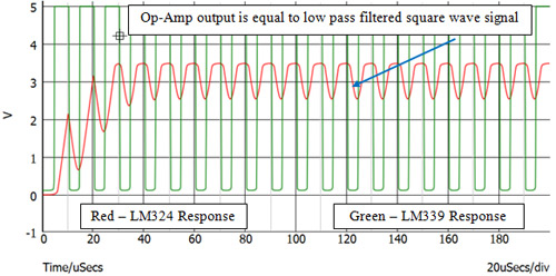
Figure 10: LM339 & LM324 Output Response Comparison – 100KHz
At 100kHz, we can get a clear idea about the comparator replacement by Op-Amp. For 100kHz operation, the LM339 Comparator still produces the required output signal with the very minimal rise and fall times. But, the LM324 Op-Amp-based comparator output is no longer the PWM waveform. Due to the reduction in gain at higher frequencies because of the Cc – Compensation Capacitor inside the Op-Amp, the Op-Amp-based Comparator circuit is operating as a “Low Pass filter” instead of a Comparator. For 100kHz frequency, the required Slew Rate is also 3.14V/us and can’t be matched with LM324 Op-Amp.
To match this requirement, the high slew rate and high bandwidth Op-Amp have to be replaced instead of LM324.
Conclusion
For comparator applications, it is always better to use a comparator instead of Op-Amp. If the Comparator is replaced with the Op-Amp for DC and very low frequency signals the Output voltage swing, Common Mode Voltage, Differential Mode Voltage, Output Configuration, and drive current are the important parameters that should be taken for analysis. Whereas, if the application is High frequency, along with the above-mentioned points, the Op-Amp Bandwidth, Slew rate, and propagation delay are the major decision-making parameters. The Large signal response which is related to defining peak voltage for Slew Rate calculation at different frequencies is also added and for higher slew rates, the Op-amp operating current consumption is also higher which increases the Op-Amp power requirement. Due to the increase in operating power, the Op-amp junction/die temperature may also increase, and thermal parameters are also taken into consideration before replacing the comparator with Op-Amp.
