
It might be surprising to know that the patent for a ‘field effect transistor’ predated the creation of the bipolar transistor by at least twenty years. However, bipolar transistors were quicker to catch on commercially, with the first chip made of bipolar transistors appearing in the 1960s, with MOSFET manufacturing technology being perfected in the 1980s and soon overtaking their bipolar cousins.
After the point contact transistor was invented in 1947, things began to move quickly. First came the invention of the first bipolar transistor in the following year. Then in 1958, Jack Kilby came up with the first integrated circuit which put more than one transistor on the same die. Eleven years later, Apollo 11 landed on the Moon, thanks to the revolutionary Apollo Guidance Computer, which was the world’s first embedded computer. It was made using primitive dual three-input NOR gate ICs, which consisted of merely 3 transistors per gate.
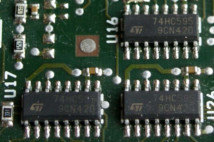
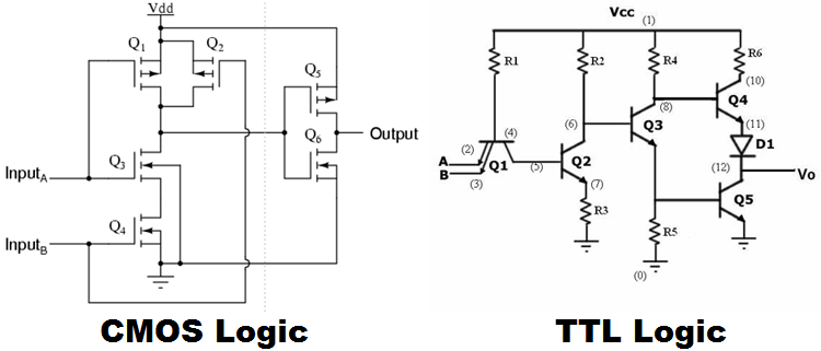
This gave rise to the popular TTL (Transistor-Transistor Logic) series of logic chips, which were constructed using bipolar transistors. These chips ran off 5V and could run at speeds up to 25MHz.
These soon gave way to Schottky clamped transistor logic, which added a Schottky diode across the base and collector to prevent saturation, which greatly reduced storage charge and decreased switching times, which in turn decreased the propagation delay caused by the storage charge.
Another series of bipolar transistor-based logic was the ECL (Emitter Coupled Logic) series which ran on negative voltages, essentially operating ‘backwards’ compared to their standard TTL counterparts ECL could run up to 500MHz.
Around this time CMOS (Complementary Metal Oxide Semiconductor) logic was introduced. It used both N-channel and P-channel devices, hence the name complementary.
TTL VS CMOS: Advantages and Disadvantages
The first and most talked about is power consumption – TTL consumes more power than CMOS.
This is true in the sense that a TTL input is just the base of a bipolar transistor, which needs some current to turn it on. The magnitude of input current depends on the circuitry inside, sinking up to 1.6mA. This becomes a problem when many TTL inputs are connected to one TTL output, which is usually just a pullup resistor or a rather poorly driven high-side transistor.
On the other hand, CMOS transistors are field-effect, in other words, the presence of an electric field at the gate is enough to influence the semiconductor channel into conduction. In theory, no current is drawn, except for the small leakage current of the gate, which is often in the order of pico- or nanoamps. However, this is not to say that the same low current consumption is true even for higher speeds. The input of a CMOS chip has some capacitance, and therefore a finite rise time. To make sure the rise time is fast at high frequency, a large current is needed, which can be in the order of several amps at MHz or GHz frequencies. This current is consumed only when the input has to change state, unlike TTL where the bias current has to be present with the signal.
When it comes to outputs, CMOS and TTL have their own advantages and disadvantages. TTL outputs are either totem pole or pullups. With totem pole, the output can swing only within 0.5V of the rails. However, the output currents are much higher than their CMOS counterparts. Meanwhile, CMOS outputs, which can be compared with voltage controlled resistors, can output within millivolts of the supply rails depending on the load. However, the output currents are limited, often being barely enough to drive a couple of LEDs.
Thanks to their smaller current requirements, CMOS logic lends itself very well to miniaturization, with millions of transistors being able to be packed into a small area without the current requirement being impractically high.
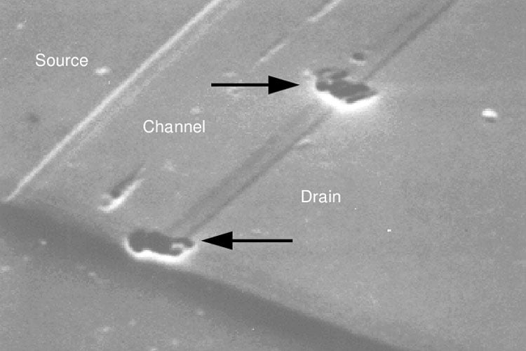
Another important advantage TTL has over CMOS is its ruggedness. Field-effect transistors depend on a thin silicon oxide layer between the gate and channel to provide isolation between them. This oxide layer is nanometers thick and has a very small breakdown voltage, rarely exceeding 20V even in high power FETs. This makes CMOS very susceptible to electrostatic discharge and overvoltage. If the inputs are left floating, they slowly accumulate charge and cause spurious output state changes, which is why CMOS inputs are usually pulled up, down, or grounded. TTL does not suffer this problem for the most part since the input is a transistor base, which acts more like a diode and is less sensitive to noise because of its lower impedance.
TTL OR CMOS? Which is Better?
CMOS logic has superseded TTL in almost every way. Though TTL chips are still available, there is no real advantage in using them.
However, TTL input levels are somewhat standardized and many logic inputs still say ‘TTL compatible’, so having a CMOS driving a TTL output stage for compatibility is not uncommon. Overall CMOS is the clear winner when it comes to utility.
The TTL logic family uses bipolar transistors to perform logic functions and CMOS uses field effect transistors. CMOS generally consumes much less power, despite being more sensitive than TTL. CMOS and TTL are not really interchangeable, and with the availability of low power CMOS chips, TTL use in modern designs is rare.
