

The ESP32 microprocessors from Espressif have quickly gained popularity and can already be found being used in many IoT projects which requires Wi-Fi or BLE Connectivity. While these processors pack in a lot of power it is often difficult to program them in the native environment for beginners and IoT enthusiasts. To tackle this problem and speed up IoT development, M5 Stack has introduced its new development kit M5Stack Core2, a feature-rich ESP32 based development module that enables you to prototype your IoT ideas right out of the box. Now, when I say feature-rich, I really mean it. This development kit has an integrated 2-inch capacitive touch screen, an in-built battery, and lots of other interesting sensors and modules packed into it. And top of all this, it can be easily programmed with Arduino IDE or micro python.
M5Stack focus on creating all-in-one stackable and modular open-source IoT Development kits, based on ESP32. M5Stack has developed a brand’s word of mouth in the development board space in the world over the last few years. Their products are beloved by most of the fans in Japan and are sold in more than 100 countries such as Japan, the United States, UK, Germany, Australia, Belgium, and so on. Its products have employed various application scenarios such as Smart Home, Smart Office, STEM Education, AI, Robotics, Industry4.0, and etc..
So, let's take a closer look at this MStack Core2 development kit, explore the various sensors and modules in it and test them using some sample Arduino programs. If you are among the early readers, you can also take part in the M5Stack Core2 giveaway, to get a chance of winning this development kit. You can either check out the below video for the complete review or if you prefer reading more, you can continue with this article.
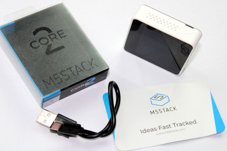
Unboxing M5Stack Core2
Starting with the unboxing, my unit was shipped with a small instruction card and the actual hardware itself. The instruction card has some useful links for some technical documents and community pages for beginners to get started. Once you slide open the main box, you will be greeted with the module itself, and then along with it, you will also have the USB Type-C cable that can be used to charge and program out development kit.
M5Stack ESP32 Development Kit – Closer Look
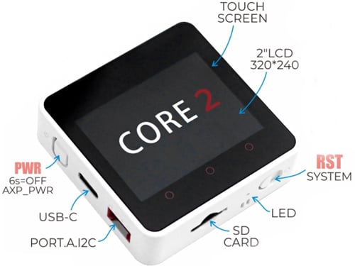
Taking a closer look on the kit, we can see that it has a neat square shape with a display on the top and buttons and slots on the side.
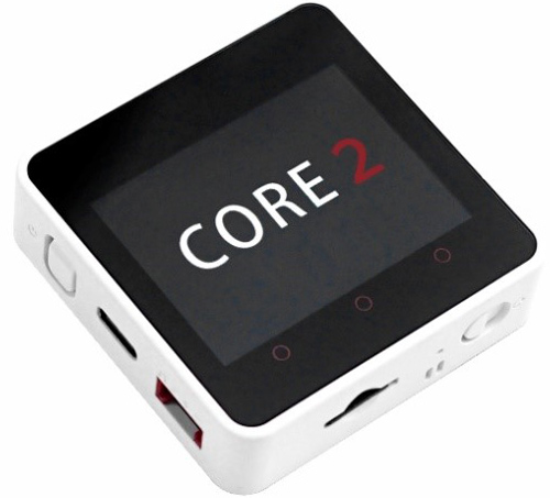
The display, as I told earlier is a 2-inch capacitive touch display with 300x240 pixel resolution. Just below the display, you can also see three capacitive touch buttons that can be programmed to work as per our requirement. We have the power button, a USB Type C USB interface port for charging and programming the device, and a grove interface connector that you can use to connect other sensors and modules if required. Moving on, on the bottom side, you can see a reset button, a green LED as a power indicator, and an SD card slot that can support up to 16G cards.
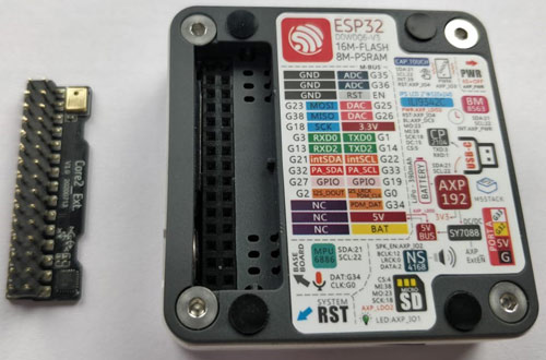
The board gets more interesting when we take a look at the backside. The sticker on the backside has a brief explanation of the features and specifications of the ICs used on this board. So let's take a look at it in the image below.
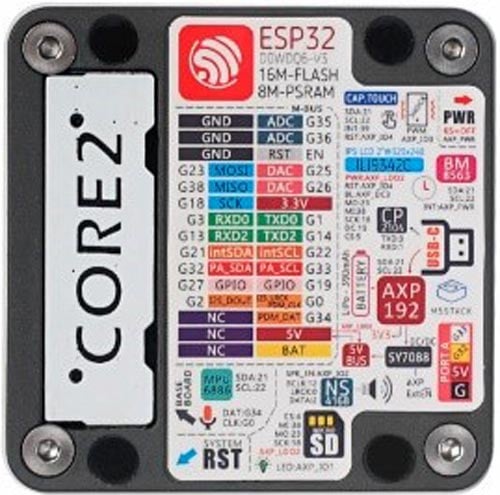
The brain behind the development kit is the ESP32 D0WDQ6 microprocessor and a dual-core Xtensa 32-bit chipset which runs on 240Mhz with 16MB Flash and 8MB PSRAM. And it goes without saying that ESP32 supports both Wi-Fi and Bluetooth (BLE) protocol. To the right, we can see to which pins display is connected to and the name of the display driver IC which is ILI9342, then we can see the marking for the power button, if we hold it for 6 seconds, the device will turn off. Then we have the BM8563 RTC IC and then the USB type C connector connected to CP2104 USB driver IC and the AXP192 Power management IC, which controls the charging of our battery and also regulates the 3.3V required for the board. Moving on, we have the SY7088 DC/DC Converter IC, which is used to set-up the voltage from the battery to 5V.
Moving on, we have NS4168 I2C Amplifier IC which is connected to an in-built speaker to play audio. And then we have the expansion board to our left, the below image shows the expansion board removed from the main board. As you see, the expansion board consists of an on-board microphone and an MPU886 6-axis IMU sensor. Once the header board is removed, the header pins on the main board will be exposed which can be used for interfacing with other modules. The pin definition of the header pins is mentioned in the Stricker itself.
M5Stack Core2 Hardware Specifications
Now we have explored the outer side of this kit, and I know its tempting to power it on and try some example programs, but before we do that, let's pop these screws and check what we have inside to take a look at our hardware. You will need an Allen key to open these screws and once you are done, just remove the back case and you should be able to see the lithium battery. The complete technical specification of the development kit is given below.
|
Resources |
Parameter |
|
ESP32-DOWD-V3 |
240 MHz dual core, 600 DMIPS, 520 kb SRAM, Wi-Fi, dual mode Bluetooth |
|
Flash |
16 MB |
|
PSRAM |
8 MB |
|
Input Voltage |
5V @ 500mA |
|
Interface |
Type C x 1, Grove ( I2C+I/O+UART) x 1 |
|
IPS LCD Screen |
2.0” @ 320*240 ILI9342C |
|
Touch Screen |
FT6336U |
|
Speaker |
1W-0928 |
|
LED |
Green Power Indicator Light |
|
Button |
Power Button, RST Button, Virtual Screen Button*3 |
|
Vibration Reminder |
Vibration Motor |
|
MIC |
SPM1423 |
|
I2C Power Amplifier |
NS4168 |
|
6-Axis IMU |
MPU6886 |
|
RTC |
BM8563 |
|
PMU |
AXP192 |
|
USB Chip |
CP2104 |
|
DC-DC Boost |
SY7088 |
|
TF Card Slot |
16G MAX. |
|
Lithium Battery |
390mAh @ 3.7V |
|
Antenna |
2.4G 3D Antenna |
|
Operating Temperature |
32°F to 104°F (0°C to 40°C) |
|
Net Weight |
52g |
|
Gross Weight |
70g |
|
Product Size |
54 x 54 x 16mm |
|
Package Size |
75 x 60 20mm |
|
Case Material |
Plastic (PC) |
M5Stack Core2 Factory Test Program
Every new unit gets shipped with a default factory test program that allows you to explore most of the features of the development kit. So now let’s power it up and check out the example program. Simply press the power button and the module boots up.
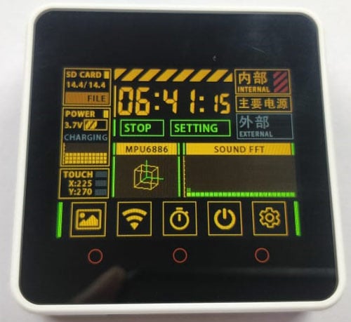
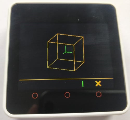
The above image shows the sample program being executed, as you can see, it displays the current time using the RTC module and also indicates the power level of the battery. Below that, we have the sound monitoring bar using which you can test your microphone. And if you click on this MPU6886, you can check out how the IMU unit is working.
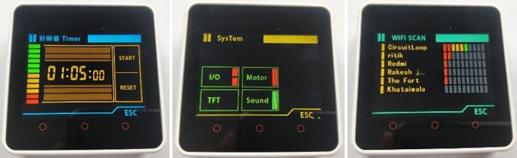
Apart from this, we can also use this Wi-Fi symbol to scan for Wi-Fi signals near us, a stopwatch timer option, and inside the setting option, we can enable the in-built motor, sound, or even test the TFT screen.
Getting Started with M5 Stack Core2
Now that we have explored the basic functions of the example program. It is time to write our own programs. For this review, I will be showing how you can use the Arduino IDE to upload code into your M5Stack Core2 Kits, but you can also use python if you are not comfortable with Arduino programming. You can also check out this official M5Stack Core2 GitHub page for more information.
To program your kit with Arduino, first, get into file preferences and the below link into the board manager's URL.
https://m5stack.oss-cn-shenzhen.aliyuncs.com/resource/arduino/package_m5stack_index.json
Then open board manager by choosing Tools -> Boards -> Board Manager. Then search for “M5Stack” and install the package.

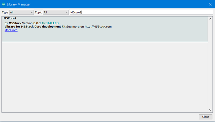
Next, open Library manager by following Sketch -> Include Library -> Manage Libraries. Search for “M5Stack2” and install the library.
With that our Arduino IDE is ready to program our M5Stack Development Kit. To program the device, just connect it to the computer using the Programming cable provided and on the Arduino IDE, select “M5Stack Core2” as the board using Tools -> Board -> M5Stack Arduino -> M5-Stack Core2, then let's open any example program from the M5Stack core2 library that we just installed here, I have opened the “Touch” example code by the following File -> examples -> M5Core2 –> Basics -> Touch.

Just make sure you have selected the right board and port and then hit on upload, you should see the development kit getting uploaded with the new program. You can use the reset button on the device to check how your new code is working, a snapshot of my development board with the example touch program is shown below.
This example program simply reads the position on the TFT screen when we touch it and display it. Now, if you want to revert back to the original example code, you can get the Core2 Factory Test Arduino Program from the linked GitHub page.
With this, I am concluding my review here. But, with a feature-packed module like this, I can already think of a few interesting IoT projects that we can build easily with this kit. What do you think? Where would you like to use this Development kit? Let me know that using the M5Stack Core2 Giveaway link and we will ship this unit to the most interesting answer.
Follow M5Stack:
Website: https://m5stack.com/
Facebook: https://www.facebook.com/M5Stack
Twitter: https://twitter.com/M5Stack
Linkedin: https://www.linkedin.com/company/m5stack
Instagram: https://www.instagram.com/m5stack
YouTube: https://www.youtube.com/m5stack
Hackster.io: https://www.hackster.io/m5stack
GitHub: https://github.com/m5stack
Document: https://docs.m5stack.com/#/
Forum: https://community.m5stack.com/
