

In this tutorial we are going to interface an Optocoupler with ATMEGA8 microcontroller. Octocouplers are fascinating devices used to isolate the electronic and electrical circuits. This simple device isolates the sensitive electronics from robust electronics like motors, yet keeping the load in control over the source.
Say we want to control the speed of an AC motor like fan, with control logic from a controller. We can fed the signal from controller to system of control which drives the motor. But during the process we also take the noise from the motor speed control system. Because its AC circuit and that too motors we will have to do a lot of noise filtration. With OPTOELECTRONICS we can avoid the direct contact of controller unit from motor driving unit. By this we avoid noise transmission between systems yet we could keep the load in total control.
OPTOELCTRONICS, as the name itself says, we will have light triggering system included. We will send signal to a light emitting device at the source end and there will be a light trigger switch at the load end. We will discuss this more in description. Here we are going to interface 4N25 a 6 pin IC to ATMEGA8 controller. When the switch is pressed at the controller end, an LED connected at load end gets turned ON.
Components Required
Hardware: ATmega8 microcontroller, Power supply (5v), AVR-ISP PROGRAMMER, 4N25 OPTOCOUPLER, 1KΩ resistor (3 pieces), LED
Software: Atmel Studio 6.1, Progisp or Flash magic.
Circuit Diagram and Explanation
The circuit diagram for OPTOCOUPLER interfacing with AVR microcontroller is shown in figure,

Before going further let’s discuss how OPTOCOUPLER works, the internal circuit of the device is shown in below picture,
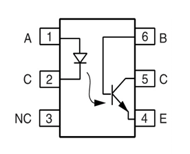
Here PINA and PINC are connected to the source side.
PINB, PINC, PINE represent the load side.
From the diagram it is clear that there is a LED (Light Emitting Diode) at the source end and there is a PHOTOTRANSISTOR at the load side. The system is framed inside a chip so the gain of PHOTOTRANSISTOR is high.
Now when a signal is passed to the LED at the source side, the LED emits light radiation, since the photo transistor is adjacent to LED, on light reception the transistor gets tuned ON. So control signal from controller gets converted to light for triggering the light sensitive load driver.
Further the chip circuit can be represented as:
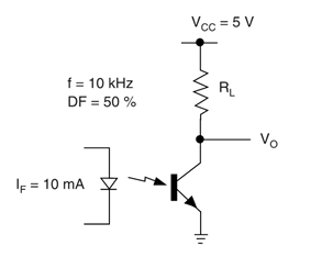
With diode at source end and transistor at load end, the above circuit makes complete sense to the name. Now the controller is provided with a button, upon firing it, the controller sends a pulse to the diode end of OPTOCOUPLER. With the load placed as an LED, the transistor in the OPTOCOUPLER drives the LED. So the LED gets turned ON.
The method of communication between OPTOCOUPLER and microcontroller is explained step by step in C code given below.
Complete Project Code
#include <avr/io.h>
//header to enable data flow control over pins
#define F_CPU 1000000UL
//telling controller crystal frequency attached

#include <util/delay.h>
//header to enable delay function in program

int main(void)
{
                DDRD = 0x00; //PORTD as input
                DDRB = 0xFF; //PORTB as ouput
    while(1)
    {
        if (bit_is_set(PIND,0)) //on button press
        {
                                                PORTB^=1<<0; //toggle logic  level at pin0 of PORTB
                                                _delay_ms(200); //delay for 200ms
                                                _delay_ms(200);
        }
    }
}
