
Hey everyone welcome back to the another tutorial of the Raspberry Pi Pico tutorial series. In this tutorial we are going to control an LED with an android app using Bluetooth and Micro Python. The HC-06 Bluetooth module is very cheap and easy to interface with the microcontrollers and it is generally implemented by using the UART communication. So, our task is to established an UART communication in between the pico board and the Bluetooth module.
Components Required for raspberry pi pico bluetooth tutorial
You need to make sure that you have the following components below before you go through this tutorial.
- Bluetooth Module HC-06
- Raspberry Pi Pico Board
- LED
- 220 Ohm Resister
- Connecting wires
- Breadboard
Raspberry Pi Pico HC-05 Bluetooth Module Circuit Connections

In the above connection diagram, you can see that the transmitter pin of the Bluetooth module has been connected to the GPIO1 that is pin number 2 of the pico board with the ORANGE Wire and the receiver pin of the Bluetooth module has been connected to the GPIO0 that is pin number 1 of the pico board with a green wire The VCC and the ground pin of the Bluetooth module is connected to the VBUS and ground pin of the pico board with the RED and BLACK wires respectively. The LED is connected the GPIO16 of the pico board through a 220 ohm Resistor.
Download and Setup the Serial Bluetooth Terminal Android App
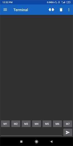
You need to download the Serial Bluetooth Terminal App from the Google Play store. When you will open the app you can see the following layout. At the bottom of the app you can see that we have some buttons labeled as “M1”, “M2”, “M3” and so on. We need to setup the “M1” as “Led On” button and “M2” as “Led Off” button.
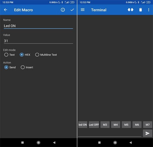
To setup the buttons you need to press and hold the button for some time. A new window will pop up as similar to the below image. You need to enter the “Name”, “Value”, “Edit mode” and “Action” as mentioned in the picture below. Then you need to repeat this step for the next button. When you finished these steps you will two customized buttons in the place of “M1” and “M2” buttons. As you can see in the second image below. So, we have done the setup of the android app as per our need.
Program for the Bluetooth communication on the Pico Board
If you are a regular reader of our Pico Tutorial Series, then you might have familiar to our GitHub Repository based on the Raspberry Pi Pico Tutorials. You need to download this Repository. When you download or clone the Repository you can find the “code” folder under the “T7_bluetooth_pico_hc05_led_blink” folder. Inside the “code” folder we have the “main.py” file. Let’s see what we have inside this file.
The main.py file
Inside the main.py file we have imported the “Pin” and “UART” classes from the “machine” library. Then We are creating an object by using the “UART(0, 9600)” where 0 is representing the UART channel. We have 2 UART channels in the Pico board. The GPIO0 and GPIO1 can be used as an UART channel 0 on the pico board. Then we have mentioned the baud rate for the UART communication that is 9600. We have assigned this UART object into a variable “uart”.
from machine import Pin,UART
uart = UART(0,9600)
Then we have declare the GPIO16 in the “LedGPIO” as an output pin of the LED. We used the “Pin(LedGPIO, Pin.OUT)” function to create an object by mentioning the “LedGPIO” pin as an OUTPUT pin. Then we have assigned the Pin() object into the “led” variable.
LedGPIO = 16
led = Pin(LedGPIO, Pin.OUT)
In the while() loop below we are using the uart.any() function to check if there is any data through the UART channel. If this any() function returns true then we are reading the data by using the uart.readline() function. Then for the first time we need to print the responsed data to see the value. In my case when I was pressing the the “ON” button of the android app, I was getting the b'\xd0' value and for “OFF” I was getting the b'\xd5' value. Then I set the “led.high()” to turn on the led and “led.low()” to turn off the led.
while True:
    if uart.any():
        command = uart.readline()
        # print(command)   # uncomment this line to see the recieved data
        if command==b'\xd0':
            led.high()
            print("ON")
        elif command==b'\xd5':
            led.low()
            print("OFF")
Uploading the Code and Control the Led with the Android App
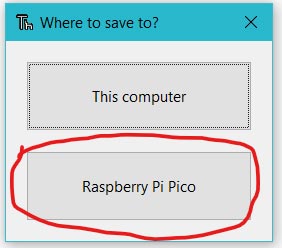
Now, in the Thonny IDE, open the “main.py” file. To begin, save the “main.py” file on the Pico board by pressing the “ctrl+shift+s” keys on your keyboard. Before saving the files, make sure your Pico board is connected to your laptop. When you save the code, a popup window will appear, as shown in the image below. You must first select the Raspberry Pi Pico, then name the file “main.py” and save it. This procedure enables you to run the program when the Pico is turned on.
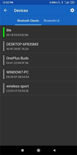
Now, we need to connect the app with our Bluetooth module. Make sure that you have uploaded the code on the pico board The code can be found in the below section. When you power up the pico board you can see the led on the Bluetooth module is blinking slowly. Now you can press the “connection button” which can be found at the top right corner of the app. A new window will pop up named as “Devices” as mentioned in the image below. You need to select your respective Bluetooth device. In my case it was “Ble” but in your case it could be “HC-06”. When you will select the device you will get connected to the Bluetooth module.
When you will have connected to the Bluetooth and press the “Led ON” or “Led OFF” buttons respectively, you could be able to see the data as “1” or “0” respectively on the terminal of the android app. You can refer the following image below.
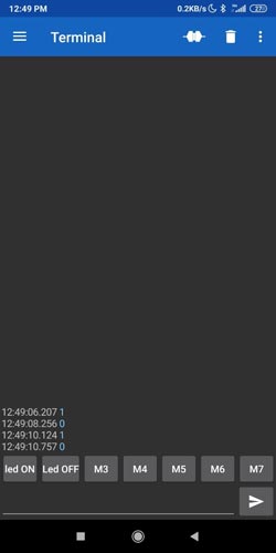
You can also see that the LED is turned on and off while you will press the “led ON” and “Led OFF” button respectively. You can watch the following video for more information.
Complete Project Code
from machine import Pin,UART
uart = UART(0,9600)
LedGPIO = 16
led = Pin(LedGPIO, Pin.OUT)
while True:
    if uart.any():
        command = uart.readline()
        # print(command)   # uncomment this line to see the recieved data
        if command==b'\xd0':
            led.high()
            print("ON")
        elif command==b'\xd5':
            led.low()
            print("OFF")
Comments
Hello Joydip
Excellent work.
Everything works for me.
I have changed the program as follows:
from machine import Pin,UART
uart = UART(0,9600) #RX-->GP0; TX-->GP01
LedGPIO = 16
led = Pin(LedGPIO, Pin.OUT)
while True:
if uart.any():
command = uart.readline()
#print(command) # uncomment this line to see the recieved data
if command==b'\x31': #Text '1' = chr(0x31)
led.high()
print("ON")
elif command==b'\x30': #Text '0' = chr(0x30)
led.low()
print("OFF")
I was trying to create an application with APP Inventor to controlling BLE, but I don't know how to do it.
I can’t thank you enough

could not get this to work for some reason the bluetooth app would sa connection failed socket might be closed. There was nothing wrong with the module I tried it with another board and it is fine. I copied and pasted the code so that was ok....any help? Thanks