
If you have a pet at your place and there is no one to feed him/her at the right time in your absence. So here we are building a IoT-based Pet Feeder which is simple, efficient, and economic. Using this automatic pet feeder, you can feed your Pet by using Blynk Mobile App or Web Dashboard from anywhere in the world. You just have to press a button or set a time and the rest of the task will be done by this machine. In this project, we are using a NodeMCU ESP8266 as the main controller, a Servo motor to operate the pet feeder and NTP servers to get the current time.
Components Required for building Pet Feeder
- NodeMCU ESP8266
- Servo Motor
Automatic Pet Feeder Circuit Diagram
Complete schematic for Automatic Pet Feeder is given below:

Connections are very simple as we are only connecting a Servo Motor with NodeMCU. Vcc (Red Wire) and GND (Brown Wire) pins of Servo are connected to 3.3V and GND of NodeMCU while the signal pin (Yellow Wire) of Servo is connected to D3 pin of NodeMCU.
Configuring Blynk for Pet Feeder
Blynk is a complete set of software for prototyping, deploying, and remotely managing connected devices at any scale, from small IoT projects to millions of commercially available connected items. It can be used to connect the hardware to the cloud and build no-code iOS, Android, and web apps to analyze real-time and historical data from devices, control them remotely from anywhere in the globe, receive vital notifications, and much more. In this project, we are going to use the Blynk mobile application for controlling the servo motor that is connected to the pet feeder setup.
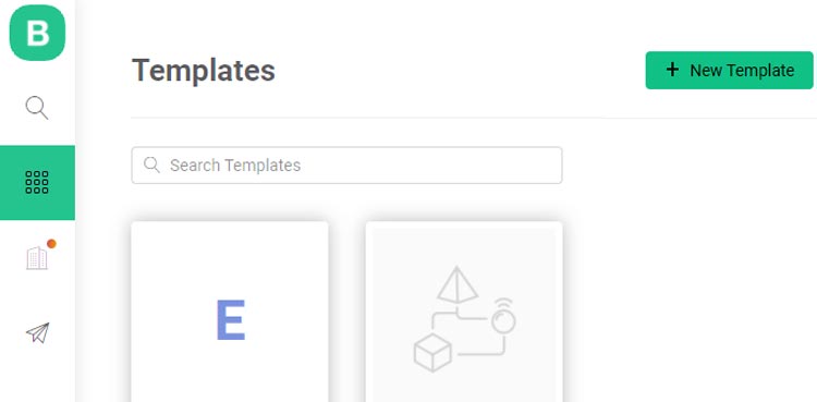
For that first, we have to create a new account for Blynk Cloud platform or you can use your old account if you already have one. Once you have logged in to your account you have to create a template where you can add multiple devices. For that click on the ‘+ New Template’ button on top right corner.
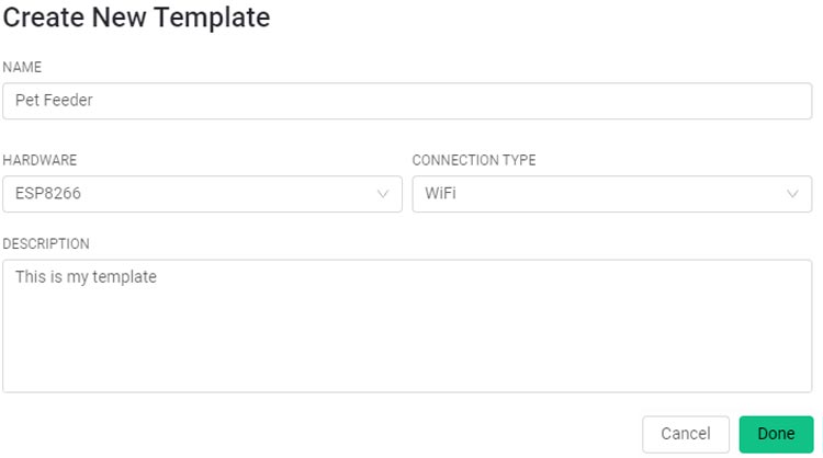
A window will pop up where you have to enter the template name, Hardware type, and connection type. Template name can be anything related to your project, Hardware type is the microcontroller board that you are using and connection type is Wi-Fi.
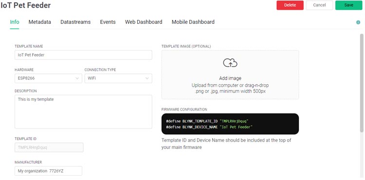
Now inside the template, we can add multiple information like device info, metadata, DataStream’s, Events, etc. In the next steps, we will fill these details one by one. So, the first tab is the device info, leave it as default.
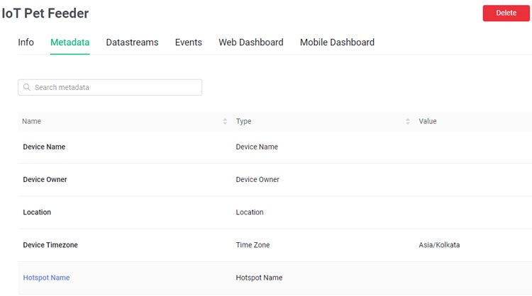
Then the second tab is the Metadata. Metadata is the additional information that we are giving to our project like Device Name, Device owner etc. This is not compulsory and you can add fill these things if you want.
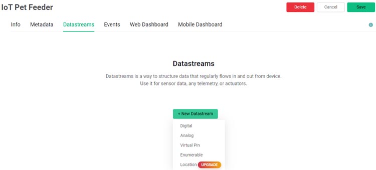
The next tab is the ‘DataStream.’ Datastreams is a way to structure data that regularly flows in and out from the device. Here we will create two data streams, one for controlling servo and the other for getting the timer data from blynk app. To create a DataStream, click on the ‘+New Datastream’ button and then select Virtual Pin.
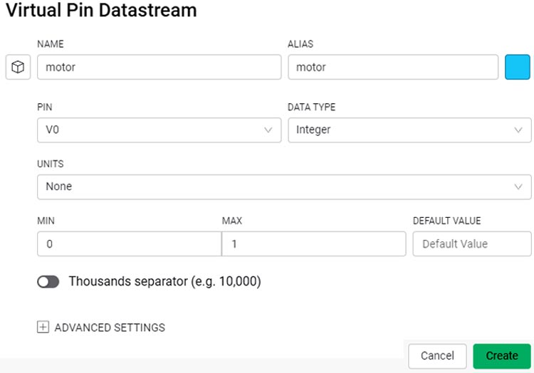
A window will pop up where you have to enter the datastream name, virtual pin, and the data type. After this click on the ‘Create’ button and follow the same procedure for creating a datastream for getting the timer values.
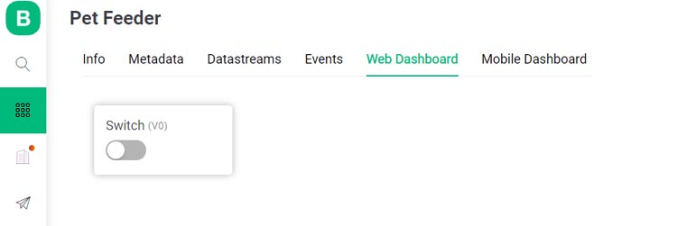
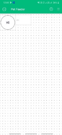
Once this is done leave the ‘Event’ tab as it is and move to the ‘Web Dashboard’ tab. In blynk 2.0 we have two types of Dashboards that are Web Dashboard and Mobile Dashboard. Both the dashboards can be configured and used separately. Web Dashboard has a limited number of widgets. You can add a switch for testing.
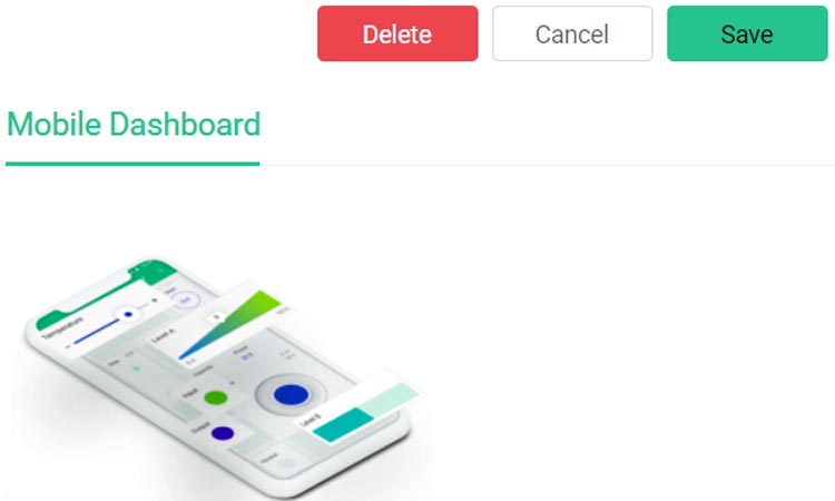
With this done the next tab is the mobile dashboard. Mobile Dashboard can be configured on Mobile only. So before moving to the mobile side first save all the changes on the cloud. For that click on the save button in the top right corner.
Now we are left with the coding part and the Mobile Dashboard. First, we will go with the coding part.
Programming NodeMCU for Pet Feeder
The complete code for this project is given at the end of the document. Here we are explaining some important lines of the code. So as usual start the code by including all the required library files. BlynkEdgent.h is the new library for Blynk 2.0 platform. "NTPClient.h" is used to get the time and date data from NTP servers. "WiFiUdp.h" library is used to handle UDP protocol like opening a UDP port, sending and receiving UDP packets, etc. While "Servo.h" is used to control the servo motor.
#include "BlynkEdgent.h"
#include <NTPClient.h>
#include <ESP8266WiFi.h>
#include <WiFiUdp.h>
#include <Servo.h>
Then in the next lines enter the Blynk template ID and Blynk Device ID. These IDs can be copied from the ‘device Info’ page on Blynk cloud platform.
#define BLYNK_TEMPLATE_ID "TMPLrKGv1gYp"
#define BLYNK_DEVICE_NAME "Pet Feeder"
Then in next line create an instance for NTP client. Inside this instance, we have to specify the address of the NTP Server we wish to use.
NTPClient timeClient(ntpUDP, "asia.pool.ntp.org", utcOffsetInSeconds);
The BLYNK_WRITE() function is used to check for incoming data at V0 and V1 Virtual pins. The virtual pin V0 is for receiving the switch state while the V1 pin is used to get the timer data from the Blynk app.
BLYNK_WRITE(V0)
{
int data = param.asInt();
if (data == 1){
  servo_1.write (45); // Servo will move to 45 degree angle.
  delay (1000);
  servo_1.write (90);  // servo will move to 90 degree angle.
}
}
BLYNK_WRITE(V1){
 time_blynk = param.asInt();
}
In the setup section, we first initialize serial communication at the baud rate of 115200 and also start the Blynk and time client communication.
void setup()
{
  Serial.begin(115200);
  delay(100);
  BlynkEdgent.begin();
  servo_1.attach(0);
  timeClient.begin();
}
Now inside the loop function, we are first getting the time data from NTP client-server and then storing this data inside HH and MM variables. The time data that we are getting from NTP client is in 24-hour format so first we changed it to 12-hour format and then we converted this hour and minute data in seconds to compare it with the timer data that we are receiving from Blynk app. If the current time and time received from Blynk app are the same then the pet feeder will be turned on and off for a specific time period.
void loop() {
  timeClient.update();
  HH = timeClient.getHours();
  int hours = HH;
    if (hours == 0) hours = 12;
    if (hours > 12) hours = hours - 12;
  MM = timeClient.getMinutes();
  final_time = 3600*hours + 60*MM;
  if (time_blynk == final_time){
  }
   BlynkEdgent.run();
}
Now select the board type that is ‘NodeMCU’ and port where the NodeMCU is connected and upload the code. With this done now, we are left with Blynk mobile application and also to add the Wi-Fi credentials to NodeMCU.
Configuring Blynk Mobile App
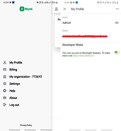
The first step will be downloading the Blynk app from Play Store and then creating a new account. You can also log in using your existing account if you have one. Now you have to enable the developer mode. Developer is a special user who has access to all of the functionality required to configure the platform for use by end-users. To enable the Developer mode click on the ‘Profile’ icon on the top left corner and then enable the Developer mode.
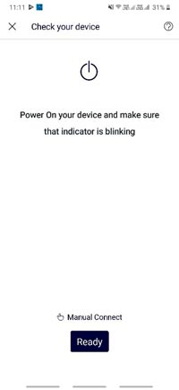
After that, you need to click on add new device button and bring the NodeMCU board closer to the phone and click on the ready button.
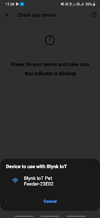
It will automatically find the hotspot created by NodeMCU board. Connect to that hotspot and then you can easily enter the Wi-Fi credentials of your router. After that click on continue and it will send the Wi-Fi credentials to NodeMCU board and we are done with adding the Wi-Fi credentials to the board.
Creating Blynk Mobile Dashboard
Now we are left with the last step that is configuring the Blynk Mobile Dashboard. For that go to the device that you just created and then click on the menu icon and you will be presented with all the widgets available.
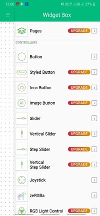
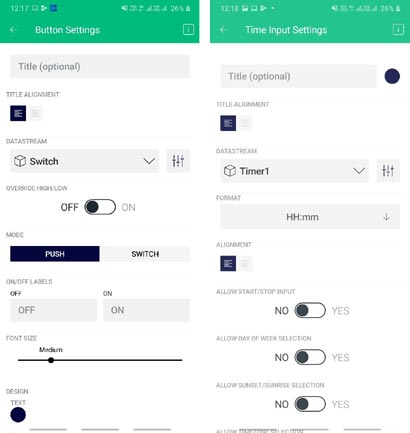
Here we will add two widgets that are Button and Timer widget. The button widget is used to control the servo manually while the timer widget is used to set the time for a particular action.
Now tap on the Button widget to configure it. Here you have to select the datastream that we created on Blynk cloud. After that tap on the Timer widget and select the datastream. You can also change other settings like widget name, color etc.
Now we have successfully configured the Blynk Mobile dashboard and the next step is building the Pet Feeder setup.
Building the Pet Feeder Setup
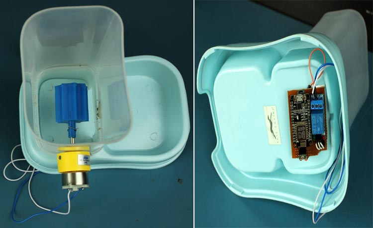
To build an automatic cat feeder we ordered a pet feeder box from amazon and modified it to fit the servo and other electronics. DC motor is placed inside the box with a 3-D printed gear attached to it. NodeMCU board is placed at the bottom of the box and this complete setup is powered using a 12V adapter.
Testing the Automatic Pet Feeder
As we have everything ready now let’s go ahead and test this Pet Feeder setup. For that I filled the Pet Feeder box with cat food and for the test run, used Blynk app installed on my mobile phone as a remote to check whether our pet feeder is dispensing food or not. As soon as I turned on the setup, the pet feeder started dispensing the cat food at a controlled rate.
Apart from the switch, we can also set a time to feed the cat using the timer widget of Blynk app. The complete testing process is shown in video attached at the bottom of the page. Hope you understood the article and learned something new. If you have any questions, drop them in the comment section below.
Complete Project Code
Edgent_ESP8266.ino
// Fill-in information from your Blynk Template here
#define BLYNK_TEMPLATE_ID "TMPLrKGv1gYp"
#define BLYNK_DEVICE_NAME "Pet Feeder"
#define BLYNK_FIRMWARE_VERSION "0.1.0"
#define BLYNK_PRINT Serial
//#define BLYNK_DEBUG
#define APP_DEBUG
// Uncomment your board, or configure a custom board in Settings.h
//#define USE_SPARKFUN_BLYNK_BOARD
//#define USE_NODE_MCU_BOARD
//#define USE_WITTY_CLOUD_BOARD
//#define USE_WEMOS_D1_MINI
#include "BlynkEdgent.h"
#include <NTPClient.h>
#include <ESP8266WiFi.h>
#include <WiFiUdp.h>
//#include <Servo.h> // including servo library.
const long utcOffsetInSeconds = 19800;
WiFiUDP ntpUDP;
NTPClient timeClient(ntpUDP, "asia.pool.ntp.org", utcOffsetInSeconds);
int HH, MM,final_time;
int time_blynk, data;
//Servo servo_1;
#define motor D0
BLYNK_WRITE(V0)
{
data = param.asInt();
}
BLYNK_WRITE(V1)
{
time_blynk = param.asInt();
Serial.print(time_blynk);
//Serial.print("Got The Time");
}
void setup()
{
Serial.begin(115200);
delay(100);
BlynkEdgent.begin();
pinMode(motor, OUTPUT);
digitalWrite(motor, LOW);
//servo_1.attach(0);
timeClient.begin();
}
void loop() {
timeClient.update();
HH = timeClient.getHours();
//Serial.print(timeClient.getHours());
int hours = HH;
if (hours == 0) hours = 12; // Midnight
if (hours > 12) hours = hours - 12;
//Serial.print(hours);
//Serial.print(":");
MM = timeClient.getMinutes();
// Serial.println(timeClient.getMinutes());
final_time = 3600*hours + 60*MM;
// Serial.println(final_time);
if (time_blynk == final_time){
digitalWrite(motor, LOW);
delay(3000);
digitalWrite(motor,HIGH);
}
if (data == 1){
digitalWrite(motor, HIGH);
delay(5000);
digitalWrite(motor,LOW);
Serial.print("Opening");
}
delay(6000);
BlynkEdgent.run();
}
I have did everything acoording to your instructions but my motor is not running when i click the push button