Hello everyone,
I`am a student and have a intership and there I need to design a step down buck converter.
I have totally no experience with buck converters so if anyone could help me.
I want to connect a 80 v Battery with a converter wich have a input voltage range of 38-66 Vdc
So the voltage of the battery must decrease tot 60 V, and that is were the buck converter comes in.
The converter itself increase the max 66Vdc to 230 Vac, three fase, 50 Hz.
The output current of the battery is 200 A
jaksonlee
Here we will have a look at the Step Down Chopper or Buck converter which reduces the input DC voltage to a specified DC output voltages.
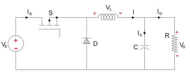 The input voltage source is connected to a controllable solid state device which operates as a switch. The solid state device can be a power MOSFET or IGBT . Thyristors are not used generally for DC-DC converters because to turn off a Thyristor in a DC-DC circuit requires another commutation which involves using another Thyristor, whereas Power MOSFET and IGBT can be turned off by simply having the voltage between the GATE and SOURCE terminals of a Power MOSFET, or, the GATE and COLLECTOR terminals of the IGBT go to zero. The second switch used is a diode. The switch and the diode are connected to a low-pass LC filter which is appropriately designed to reduce the current and voltage ripples. The load is a purely resistive load. The input voltage is constant and the current through load is also constant. The load can be seen as current source. The controlled switch is turned on and off by using Pulse Width Modulation(PWM). PWM can be time based or frequency based. Frequency based modulation has disadvantages like a wide range of frequencies to achieve the desired control of the switch which in turn will give the desired output voltage.

John_Kripto
Joined August 11, 2018 35Saturday at 01:52 PM
Hi nick, not to sound harsh here but building a 200A step-down switching conveter for a newbie is not a going to be easy. Make sure if your output current really has to be 200A.
You can start by learning the basics of Buck regulators here https://circuitdigest.com/tutorial/switching-buck-regulator-design-basics-and-efficiency and then build a simple buck converter like this one https://circuitdigest.com/electronic-circuits/12v-to-5v-buck-converter-circuit-diagram
Once you understand the concept you can then try designign a higher power converter, the number of power electronic switchs and its driving technique will vary for a higher power converter